2.7.3.3. Tables for geometry representation
The representation of the geometry stored in table SURFACE_GEOMETRY differs substantially from the UML chart explained in the CityGML specification; nevertheless, it offers about the same functionality.
SURFACE_GEOMETRY, SURFACE_GEOMETRY_SEQ
In the database schema the geometry consists of planar surfaces which correspond each to one entry in the table SURFACE_GEOMETRY. The surface-based geometry is stored as attribute GEOMETRY (in each case exactly one planar polygon, possibly including holes). The implicit geometry is stored as attribute IMPLICIT_GEOMETRY. The volumetric geometry is stored as attribute SOLID_GEOMETRY and its boundary surfaces (outer shell) will be stored as attribute GEOMETRY as well. Any surface may have textures or a colour on both sides. Textures are stored within the tables which implement the appearance model (cf. Section 2.6.3).
The geometry information in the fields GEOMETRY and IMPLICIT_GEOMETRY of the table SURFACE_GEOMETRY is limited as follows:
Oracle
|
PostGIS
|
- SDO_GTYPE must have the type Polygon, i.e. a
polygon with 3D coordinates (SDO_GTYPE = 3003)
- SDO_ETYPE must be 1003/2003 with
SDO_INTERPRETATION = 1 (i.e. polygon with
3D coordinates in the boundary, bounded just by
linesegments, possibly including holes)
- In addition Oracle allows the representation
of a rectangle by two corner points
(SDO_ETYPE=1003/2003,
with SDO_INTERPRETATION = 3)
- SDO_SRID of implicit geometries can be
any SRID Oracle supports. No spatial index
is defined on the column by default.
|
- Only POLYGON Z is allowed, i.e. a polygon
with 3D coordinates
- Polygons might have holes
- The IMPLICIT_GEOMETRY column has no
SRID defined. Thus, entries in that column
will have the SRID 0 automatically
|
A solid is the basis for 3-dimensional geometry. The extent of a solid is defined by the boundary surfaces (outer shell). A shell is represented by a composite surface, where every shell is used to represent a single connected component of the boundary of a solid. It consists of a composite surface (a list of OrientableSurfaces) connected in a topological cycle. Unlike a ring, a shell’s elements have no natural sort order. Like rings, shells are simple. The geometry in the field SOLID_GEOMETRY of the table SURFACE_GEOMETRY is limited as follows:
Oracle
|
PostGIS
|
- SDO_GTYPE must have the type Solid, i.e. a solid
with 3D coordinates (SDO_GTYPE = 3008)
- SDO_ETYPE must be 1007 (simple solid) or
1008 (composite solid)
- A simple solid can be represented by using
several polygons as its boundary
(SDO_ETYPE=1007,
with SDO_INTERPRETATION = 1)
- The composite solid can be constructed with
a number of simple solids, e.g. a composite
solid with 4 simple solids (SDO_ETYPE=1008,
with SDO_INTERPRETATION = 4)
|
- Only POLYHEDRALSURFACE is allowed, i.e.
the outer shell of a solid with 3D coordinates
- A simple polyhedral surface can be represented
by using several polygons as its boundary
|
Surfaces can be aggregated to form a complex of surfaces or the boundary of a volumetric object. The aggregation of multiple surfaces, e.g. F1 to Fn, (IDs 6 to 10 in Fig. 2.31 / Fig. 2.32) is realized the way that the newly created surface tuple Fn+1 (ID 2) is not assigned a geometry (cf. Table 2.8). Instead, the PARENT_ID of the surfaces F1 to Fn refer to the ID of Fn+1.
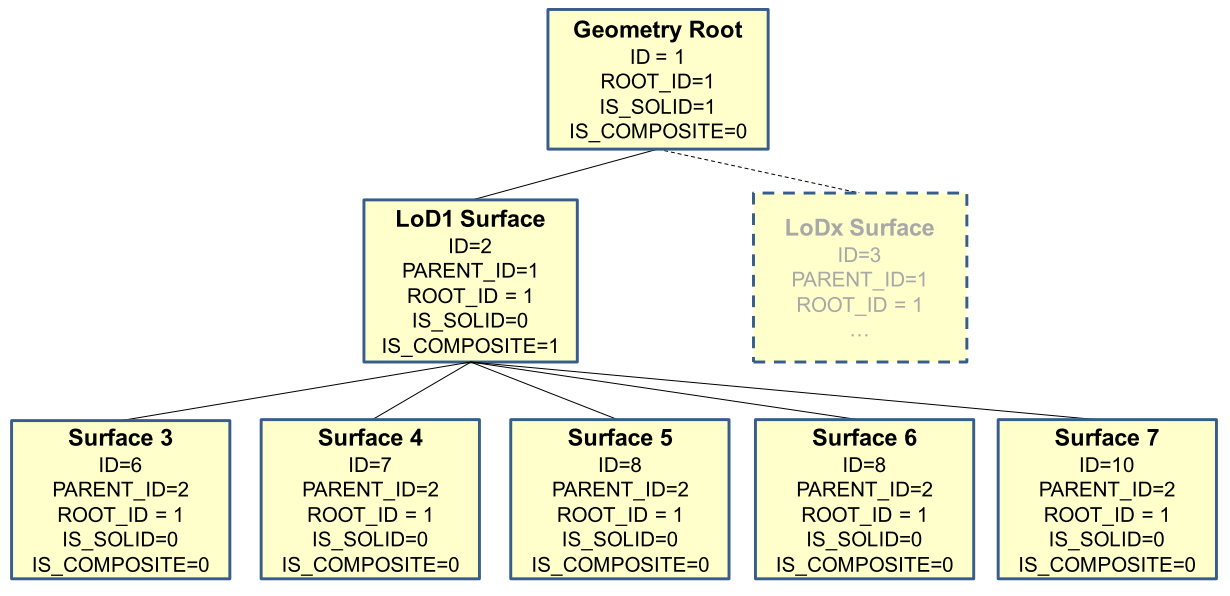
Fig. 2.31 Geometry hierarchy for the solid geometry shown in Fig. 2.32
In addition, a further tuple (ID 1) is introduced, which represent the solid and defines the root element of the whole aggregation structure. Each surface references to its root, using the ROOT_ID attribute. This information has big influence on the system performance, as it allows to avoid recursive queries. If e.g. the retrieval of all surface elements forming a specific building is of importance, simply those tuples have to be selected which contain the related ROOT_ID. On the downside there also follows the limitation that each tuple in SURFACE_GEOMETRY can only belong to one aggregate.
Various flags characterise the type of aggregation: IS_TRIANGULATED denotes a TriangulatedSurface, IS_SOLID distinguishes between surface (0) and solid (1), and IS_COMPOSITE defines whether this is an aggregate (e.g. MultiSolid, MultiSurface) or a composite (e.g., CompositeSolid, CompositeSurface).
Based on these flags the geometry types listed in Table 2.8 can be distinguished. To distinguish a MultiSolid from a MultiSurface its child elements have to be analysed: In case the child is a Solid, the geometry can be identified as MultiSolid.
isSolid
|
isComposite
|
isTriangulated
|
Geometry
|
SOLID_
GEOMETRY
|
|
Polygon, Triangle,
Rectangle
|
GEOMETRY
|
NULL
|
|||
MultiSurface
|
NULL
|
NULL
|
|||
CompositeSurface
|
✔
|
NULL
|
NULL
|
||
TriangulatedSurface
|
✔
|
NULL
|
NULL
|
||
Solid
|
✔
|
NULL
|
GEOMETRY
|
||
MultiSolid
|
NULL
|
NULL
|
|||
CompositeSolid
|
✔
|
✔
|
NULL
|
GEOMETRY
|
Aggregated surfaces can be grouped again with other (compound) surfaces, by generating a common parent. This way, arbitrary aggregations of Surfaces, CompositeSurfaces, Solids, CompositeSolids can be formed. Since all tuples in an aggregated geometry refer to the same ROOT_ID all tuples can be retrieved efficiently from the table by selecting those tuples with the same ROOT_ID.
The aggregation schema allows for the definition of nested aggregations (hierarchy of components). For example, a building geometry (CompositeSolid) can be composed of the house geometry (CompositeSolid) and the garage geometry (Solid), while the house’s geometry is further decomposed into the roof geometry (Solid) and the geometry of the house body (Solid).
In addition, the foreign key CITYOBJECT_ID refers directly to the CityGML features to which the geometry belongs. In order to select all geometries forming the city object one only has to select those with the same CITYOBJECT_ID.
In order to provide a unique identifier in table SURFACE_GEOMETRY, the next available ID value is provided by the sequence SURFACE_GEOMETRY_SEQ.
Example: The geometry shown in the figure below consists of seven surfaces which form a volumetric object. In the table it is represented by the following rows:
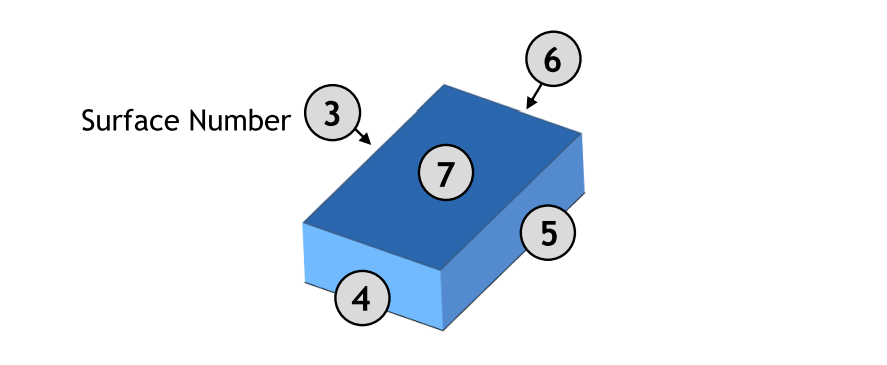
Fig. 2.32 LoD 1 building - closed volume bounded by a CompositeSurface which consists of single polygons
ID
|
GMLID
|
PARENT_
ID
|
ROOT_
ID
|
IS_
SOLID
|
IS_COM
POSITE
|
GEOMETRY
|
SOLID_
GEOMETRY
|
1
|
UUID
_lod1
|
NULL
|
1
|
1
|
0
|
NULL
|
GEOMETRY
for Solid
|
2
|
lod1
Surface
|
1
|
1
|
0
|
1
|
NULL
|
NULL
|
3
|
Left1
|
2
|
1
|
0
|
0
|
GEOMETRY
for surface 3
|
NULL
|
4
|
Front1
|
2
|
1
|
0
|
0
|
GEOMETRY
for surface 4
|
NULL
|
5
|
Right1
|
2
|
1
|
0
|
0
|
GEOMETRY
for surface 5
|
NULL
|
6
|
Back1
|
2
|
1
|
0
|
0
|
GEOMETRY
for surface 6
|
NULL
|
7
|
Roof1
|
2
|
1
|
0
|
0
|
GEOMETRY
for surface 7
|
NULL
|
In addition, two further attributes are included in SURFACE_GEOMETRY: IS_XLINK and IS_REVERSE.
IS_XLINK
CityGML allows for sharing of geometry objects between different geometries or different thematic features using the XLink concept of GML3. For this purpose, the geometry object to be shared is assigned an unique gml:id which may be referenced by a GML geometry property element through its xlink:href attribute. This concept allows for avoiding data redundancy. Furthermore, CityGML does not employ the built-in topology package of GML3 but rather uses the XLink concept for the explicit modelling of topology (see [GKCN2008] p. 25).
Although an XLink can be seen as a pointer to an existing geometry object the SURFACE_GEOMETRY table does not offer a foreign key attribute which could be used to refer to another tuple within this table. The main reason for this is that the referenced tuple typically belongs to a different geometry aggregate, e.g. a different gml:Solid object, and thus contains different values for its ROOT_ID and PARENT_ID attributes. Therefore, foreign keys would violate the aggregation mechanism of the SURFACE_GEOMETRY table.
The recommended way of resolving of XLink references to geometry objects requires two steps: First, the referenced tuple of the SURFACE_GEOMETRY table has to be identified by searching the GMLID column for the referenced gml:id value. Second, all attribute values of the identified tuple have to be copied to a new tuple. However, the ROOT_ID and PARENT_ID of this new tuple have to be set according to the context of the referencing geometry property element.
Please note:
- If the referenced tuple is the top of an aggregation (sub)hierarchy within the SURFACE_GEOMETRY table, then also all nested tuples have to be recursively copied and their ROOT_ID and PARENT_ID have to be adapted.
- Copying existing entries of the SURFACE_GEOMETRY table results in tuples sharing the same GMLID. Thus, these values cannot be used as a primary key.
When it comes to exporting data to a CityGML instance document, XLink references can be rebuilt by keeping track of the GMLID values of exported geometry tuples. Generally, for each and every tuple to be exported it has to be checked whether a geometry object with the same GMLID value has already been processed. If so, the export routine should make use of an XLink reference.
However, checking the GMLID of each and every tuple may dramatically slow down the export process. For this reason, the IS_XLINK flag of the SURFACE_GEOMETRY has been introduced. It may be used to explicitly mark just those tuples for which a corresponding check has to be performed. The IS_XLINK flag should be used in the following manner. The Importer/Exporter provides a corresponding reference implementation.
- During import
- By default, the IS_XLINK flag is set to “0”.
- If existing tuples have to be copied due to an XLink reference, IS_XLINK has to be set to “1” for each and every copy. Please note, that this rule comprises all copies of nested tuples.
- Furthermore, IS_XLINK has to be set to “1” on the original tuple addressed by the XLink reference. If this tuple is the top of an aggregation (sub)hierarchy, IS_XLINK remains “0” for all nested tuples.
- During export
- The export process just has to keep track of the GMLID values of those geometry tuples where IS_XLINK is set to “1”.
- When it comes to exporting a tuple with IS_XLINK set to “1”, the export process has to check whether it already came across the same GMLID and, thus, can make use of an XLink reference in the instance document.
- For each tuple with IS_XLINK=0 no further action has to be taken.
Especially due to (2c), the IS_XLINK attribute helps to significantly speed up the export process when rebuilding XLink references. Please note, that this is the only intended purpose of the IS_XLINK flag.
IS_REVERSE
The IS_REVERSE flag is used in the context of gml:OrientableSurface geometry objects. Generally, an OrientableSurface instance cannot be represented within the SURFACE_GEOMETRY table since it cannot be encoded using the flags IS_SOLID, IS_COMPOSITE, and IS_TRIANGULATED (cf. Table 5). However, the IS_REVERSE flag is used to encode the information provided by an OrientableSurface and to rebuild OrientableSurfaces during data export.
According to GML3, an OrientableSurface consists of a base surface and an orientation. If the orientation is “+”, then the OrientableSurface is identical to the base surface. If the orientation is “-“, then the OrientableSurface is a reference to a surface with an up-normal that reverses the direction for this OrientableSurface.
During import, only the base surfaces are written to the SURFACE_GEOMETRY table. The following rules have to be obeyed in the context of OrientableSurface:
- If the orientation of the OrientableSurface is “-“, then
- The direction of the base surface has to be reversed prior to importing it (generally, this means reversing the order of coordinate tuples).
- The IS_REVERSE flag has to be set to “1” for the corresponding entry in the SURFACE_GEOMETRY table.
- If the base surface is an aggregate, then steps (a) and (b) have to be recursively applied for all of its surface members.
- If the OrientableSurface is identical to its base surface (i.e., if its orientation is “+”), then the base surface can be written to the SURFACE_GEOMETRY table without taking any further action. The IS_REVERSE flag has to be set to “0” (which is also the default value).
- Please note, that it is not sufficient to just rely on the gml:orientation attribute of an OrientableSurface in order to determine its orientation since OrientableSurfaces may be arbitrarily nested.
Flipping the direction of the base surface in step (1a) is essential in order to guarantee that the objects stored within the GEOMETRY column are always correctly oriented. This enables applications to just access the GEOMETRY column without having to interpret further attributes of the SURFACE_GEOMETRY table. For example, in the case of a viewer application this allows for a fast rendering of a virtual 3d city scene.
When exporting CityGML instance documents, the IS_REVERSE flag can be used to rebuild OrientableSurface in the following way:
- If the IS_REVERSE flag is set to “1” for a table entry, the exporter routine has to reverse the direction of the corresponding surface object prior to exporting it (again, this means reversing the order of coordinate tuples).
- The surface object has to be wrapped by a gml:OrientableSurface object with gml:orientation=”-”.
- If the surface object is an aggregate, its surface members having the same value for the IS_REVERSE flag may not be embraced by another OrientableSurface. However, if the IS_REVERSE value changes, e.g., from “1” for the aggregate to “0” for the surface member, also the surface member has to be embraced by a gml:OrientableSurface according to (2). Since there might be nested structures of arbitrary depth this third rule has to be applied recursively.
Like with the IS_XLINK flag, the Importer/Exporter tool provides a reference implementation of the IS_REVERSE flag.