2.7.3.5. Building Model
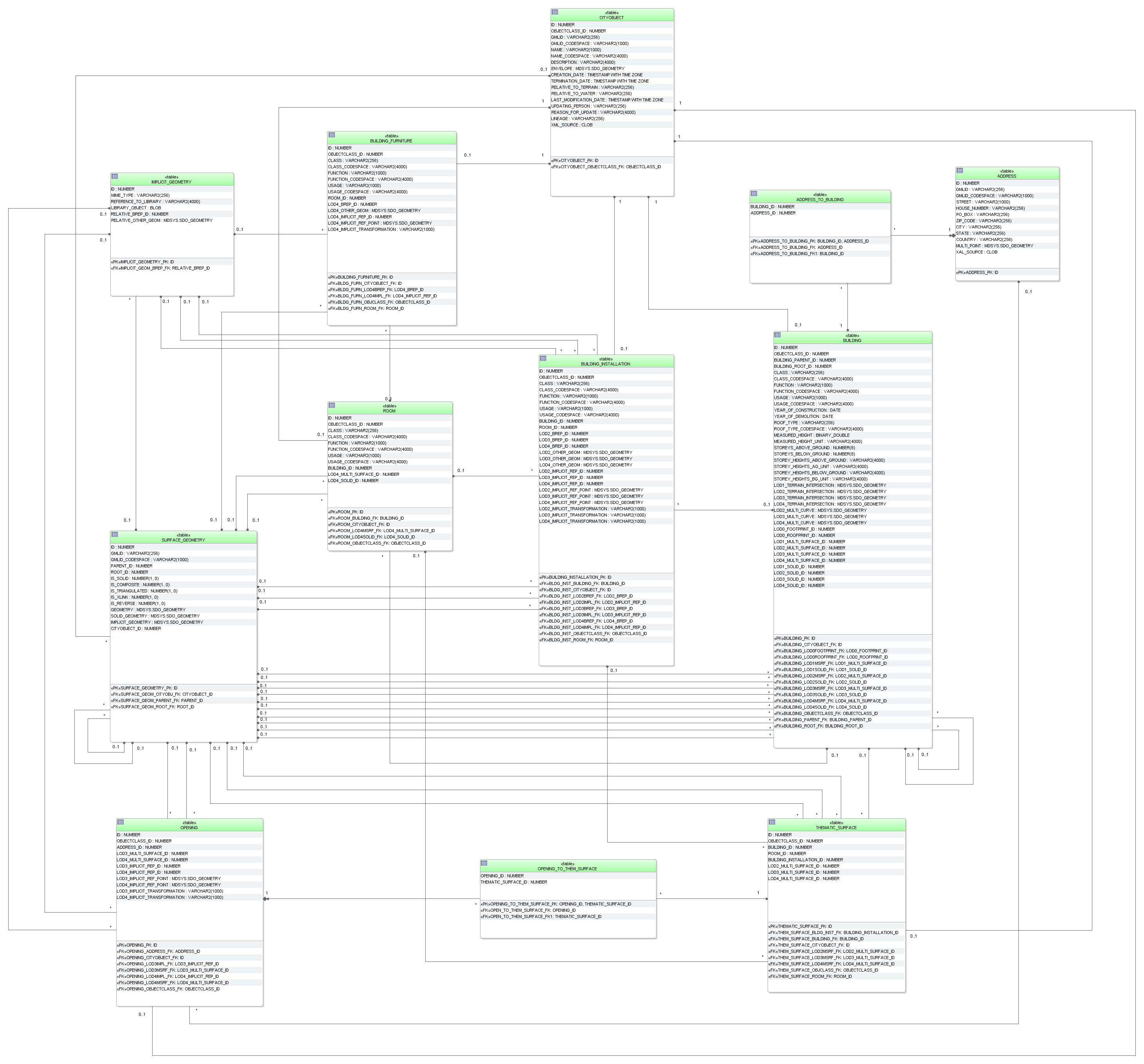
Fig. 2.44 Building database schema
BUILDING
The building model, described in Section 2.6.4.2 at the conceptual level, is realised by the tables shown in Fig. 2.44. The three CityGML classes AbstractBuilding, Building and BuildingPart are merged into the single table BUILDING. They can be distinguished on behalf of the OBJECTCLASS_ID. The subclass relationship with CITYOBJECT arises from using identical IDs, i.e. for each tuple in BUILDING there must exist a tuple within CITYOBJECT with the same ID.
ID
|
BUILDING_
PARENT_ID
|
BUILDING_
ROOT_ID
|
…
|
LOD0_
FOOT
PRINT_ID
|
…
|
LOD1_
MULTISUR
FACE_ID
|
…
|
LOD4_
SOLID_
ID
|
1
|
NULL
|
1
|
10
|
NULL
|
NULL
|
|||
2
|
1
|
1
|
NULL
|
20
|
NULL
|
|||
3
|
1
|
1
|
NULL
|
30
|
NULL
|
|||
4
|
2
|
1
|
NULL
|
NULL
|
400
|
|||
5
|
2
|
1
|
NULL
|
NULL
|
500
|
|||
6
|
3
|
1
|
NULL
|
NULL
|
600
|
|||
7
|
3
|
1
|
NULL
|
NULL
|
700
|
The component hierarchy within a building is realized by the foreign key BUILDING_PARENT_ID which refers to the superordinate building (aggregate) and contains NULL, if such does not exist. This way, a tree-like structure arises also for building aggregates. BUILDING_PARENT_ID points at the predecessor in the tree. The foreign key BUILDING_ROOT_ID refers directly to the top level (root) of a building tree. In order to select all parts forming a building one only has to select those with the same BUILDING_ROOT_ID (cf. Table 2.11).
The meaning and the name of most fields are identical to those of the attributes in the UML diagram (cf. Fig. 2.7). Like for CityObjectGroups there are additional _CODESPACE columns for the attributes class, function and usage. A _CODESPACE column is also added for the roofType attribute as it is specified as gml:CodeType in CityGML. For every attribute including measure information like measuredHeight or storeyHeightsAboveGround etc. an additional _UNIT column is provided to specify the unit of measurement.
Geometry is represented by several foreign keys LOD0_FOOTPRINT_ID, LOD0_ROOFPRINT_ID, LODx_MULTI_SURFACE_ID (1≤ x ≤ 4), and LODx_SOLID_ID (1 ≤ x ≤ 4) which refer to entries in the SURFACE_GEOMETRY table and represent each LoD’s surface geometry.
Optionally the geometry of the terrain intersection curve is stored in the attribute LODx_TERRAIN_INTERSECTION (1 ≤ x ≤ 4) using database geometry type (see Table 2.12). Additional line-typed building elements such as antennas are optionally modelled by the attribute LODx_MULTI_CURVE (1 ≤ x ≤ 4, using the same database geometry like for terrain intersection curves).
Oracle
|
PostGIS
|
- SDO_GTYPE must have the type
MultiCurve/MultiLine, i.e. a composite
geometry of different line string segments
with 3D coordinates (SDO_GTYPE = 3006)
- SDO_ETYPE must be 1 (straight line segments)
as curved geometries are not allowed in CityGML
and SDO_INTERPRETATION must be 2
|
- Only MULTILINESTRING Z is allowed, i.e. a
composite geometry of different line string
segments with 3D coordinates
- The geometry type MULTICURVE is not used as
CityGML does not allow geometry with arcs
|
THEMATIC_SURFACE
The table THEMATIC_SURFACE represents thematic boundary features. CityGML class _BoundarySurface has a number of concrete subclasses representing different types of surfaces. One possibility would be to represent each of these classes by its own table. Here, we choose the approach to create one table representing all those classes. No own tables for the subclasses of _BoundarySurface were created in the relational schema; instead, the type of the boundary surface is given by the foreign key OBJECTCLASS_ID in the table THEMATIC_SURFACE. Allowed integer values:
- 30 (CeilingSurface)
- 31 (InteriorWallSurface)
- 32 (FloorSurface)
- 33 (RoofSurface)
- 34 (WallSurface)
- 35 (GroundSurface)
- 36 (ClosureSurface)
- 60 (OuterCeilingSurface)
- 61 (OuterFloorSurface)
If a CityGML ADE is used that extends any of the classes named above, further values for OBJECTCLASS_ID may be added by the ADE manager. Their concrete numbers depend on the ADE registration (cf. Section 3.9.3.3.1).
The aggregation relation between buildings and the corresponding boundary surfaces results from the foreign key BUILDING_ID of the table THEMATIC_SURFACE which refers to the ID of the respective building. The same applies to references between surfaces of building installations (BUILDING_INSTALLATION_ID) and rooms (ROOM_ID). Thematic surfaces and the corresponding parent feature should share their geometry: the geometry should be defined only once and be used conjointly as XLinks. The SURFACE_GEOMETRY, which for example geometrically defines a roof, should at the same time be a part of the volume geometry of the parent feature the roof belongs to.
Example:
In Fig. 2.45, a building geometry is shown consisting of several surface geometries enclosing the outer building shell. Please note that the left wall (ID 5) is composed of two polygons (IDs 11 and 12) and that the roof is split into a left and a right part (IDs 20 and 21) each of which again consists of two polygons, the roof surface and an overhanging part. In the SURFACE_GEOMETRY table (cf. Table 2.13), the attribute IS_COMPOSITE is set to 1 for the tuples with IDs 5, 20 and 21 characterising them as composite surfaces. The surface geometries are semantically classified as roof, wall or ground surface by adding an entry into the THEMATIC_SURFACE table and linking this entry with the corresponding geometry tuple in SURFACE_GEOMETRY. In Table 2.14, an excerpt of the THEMATIC_SURFACE table is depicted. The tuple with ID 70 represents a RoofSurface by setting the OBJECTCLASS_ID attribute to the value 33. For its geometry, the tuple references ID 21 in the SURFACE_GEOMETRY table via the LOD2_MULTI_SURFACE_ID attribute.
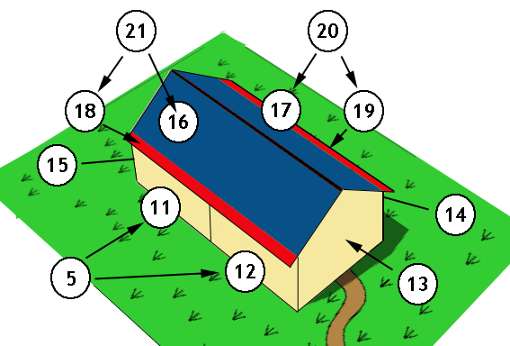
Fig. 2.45 LoD2 building with roof overhangs, highlighted in red
ID
|
GMLID
|
PARENT_
ID
|
ROOT_
ID
|
IS_
SOLID
|
IS_
COMPO
SITE
|
IS_
XLINK
|
GEOMETRY
|
3
|
UUID_LoD2
|
NULL
|
3
|
0
|
0
|
0
|
NULL
|
5
|
Left_Wall
|
3
|
3
|
0
|
1
|
0
|
NULL
|
11
|
Left_Wall_1
|
5
|
3
|
0
|
0
|
0
|
Geometry
comp (5-1)
surface 11
|
12
|
Left_Wall_2
|
5
|
3
|
0
|
0
|
0
|
Geometry
comp (5-2)
surface 12
|
13
|
Front
|
3
|
3
|
0
|
0
|
0
|
Geometry
surface 13
|
14
|
Right_Wall
|
3
|
3
|
0
|
0
|
0
|
Geometry
surface 14
|
15
|
Back
|
3
|
3
|
0
|
0
|
0
|
Geometry
surface 15
|
16
|
Roof_part_1
|
21
|
3
|
0
|
0
|
1
|
Geometry
surface 16
|
17
|
Roof_part_2
|
20
|
3
|
0
|
0
|
1
|
Geometry
surface 17
|
18
|
Overhang_1
|
21
|
3
|
0
|
0
|
0
|
Geometry of
overhang 18
|
19
|
Overhang_2
|
20
|
3
|
0
|
0
|
0
|
Geometry of
overhang 19
|
20
|
Roof_right
|
3
|
3
|
0
|
1
|
0
|
NULL
|
21
|
Roof_left
|
3
|
3
|
0
|
1
|
0
|
NULL
|
…
|
…
|
…
|
…
|
…
|
…
|
…
|
…
|
30
|
UUID_Solid
|
NULL
|
30
|
1
|
0
|
0
|
NULL
|
31
|
UUID_CS
|
30
|
30
|
0
|
1
|
0
|
NULL
|
32
|
Roof_part_1
|
31
|
30
|
0
|
0
|
1
|
Geometry
surface 16
|
33
|
Roof_part_2
|
31
|
30
|
0
|
0
|
1
|
Geometry
surface 17
|
…
|
…
|
…
|
…
|
…
|
…
|
…
|
…
|
ID
|
…
|
OBJECTCLASS_ID
|
BUILDING_ID
|
ROOM_ID
|
LOD2_MULTI_
SURFACE_ID
|
…
|
…
|
…
|
…
|
…
|
…
|
…
|
…
|
70
|
…
|
33
|
1
|
NULL
|
21
|
…
|
…
|
…
|
…
|
…
|
…
|
…
|
…
|
In addition to thematic boundary surfaces, assume that we also want to represent the building volume as separate solid geometry that is stored with the building itself. For this purpose, another tuple with ID 30 is added to the SURFACE_GEOMETRY table whose IS_SOLID attribute is set to 1. This tuple is referenced from BUILDING using the LOD2_SOLID_ID attribute (cf. Table 2.15).
According to the CityGML specification, the surface geometries forming the solid geometry shall reference the geometries of the thematic boundary surfaces using GML’s XLink mechanism. Therefore, the referenced geometries have to be copied and inserted as new tuples into SURFACE_GEOMETRY. Moreover, the IS_XLINK flag has to be set to 1 for the referenced geometries and their copies (see Section 2.7.3.3 for details). In Table 2.13, this is illustrated for the geometries with ID 32 and 33, which are copies of the tuples with ID 16 and 17 respectively. Note, that the overhanging roof parts (IDs 18 and 19) are not referenced by the solid geometry, because they are dangling surfaces and not part of the volume.
ID
|
…
|
BUILDING_ROOT_ID
|
…
|
LOD1_SOLID_ID
|
LOD2_SOLID_ID
|
…
|
…
|
…
|
…
|
…
|
…
|
…
|
…
|
1
|
…
|
1
|
…
|
NULL
|
30
|
…
|
…
|
…
|
…
|
…
|
…
|
…
|
…
|
BUILDING_INSTALLATION
The UML classes BuildingInstallation and IntBuildingInstallation are realized by the single table BUILDING_INSTALLATION. Internal and external objects are distinguished by the attribute OBEJCTCLASS_ID (external 27, internal 28). The relation to the corresponding parent feature arises from the foreign key BUILDING_ID or ROOM_ID, whereas the surface based geometry in LoD 2 to 4 is given via the foreign keys LODx_BREP_ID (2 ≤ x ≤ 4) referring to the table SURFACE_GEOMETRY.
Additional point- or line-typed building installation elements such as antennas can be modelled by the attribute LODx_OTHER_GEOM (2 ≤ x ≤ 4) using the database geometry type (any GTYPE, ETYPE etc. in Oracle and GEOMETRY Z in PostGIS). Since CityGML 2.0.0 building installations can also be represented by using prototypes which are stored as library objects implicitly. The information needed for mapping prototype objects to buildings consists of a base point geometry (LODx_IMPLICIT_REF_POINT (2 ≤ x ≤ 4)), a transformation matrix (LODx_IMPLICIT_TRANSFORMATION (2 ≤ x ≤ 4)), which is stored as a string, and a foreign key reference to the IMPLICIT_GEOMETRY table (LODx_IMPLICIT_REP_ID (2 ≤ x ≤ 4)) where a reference to an explicit surface based geometry in LoD 2 to 4 is saved.
OPENING
Openings (CityGML class Opening) are represented by the table OPENING and are only allowed in LoD3 and 4. No individual tables are created for the subclasses. Instead, the differentiation is achieved by the foreign key OBJECTCLASS_ID which refers to the attribute ID of the (meta) table OBJECTCLASS. Valid integer values are 39 (Door) and 38 (Window). If a CityGML ADE is used that extends any of the two classes Door or Window, further values for OBJECTCLASS_ID may be added by the ADE manager. Their concrete numbers depend on the ADE registration (cf. Section 3.9.3.3.1).
Table OPENING_TO_THEM_SURFACE associates an opening ID in table OPENING with a thematic surface ID in table THEMATIC_SURFACE representing the m:n relation between both tables. An address can be assigned to a door (table OPENING) by the foreign key ADDRESS_ID in the table OPENING. Furthermore, addresses may be assigned to buildings (see table ADDRESS for detailed information).
Like with building installations openings can be modelled via implicit geometry since CityGML 2.0.0. Thus, the OPENING table does contain the columns LODx_IMPLICIT_REP_ID, LODx_IMPLICIT_REF_POINT and LODx_IMPLICIT_TRANSFORMATION, too.
ROOM
Room objects are allowed in LoD4 only. Therefore, the only keys LOD4_MULTI_SURFACE_ID and LOD4_SOLID_ID are referring to the table SURFACE_GEOMETRY. Additionally, the foreign keys to tables BUILDING and CITYOBJECT are necessary to map the relationship to these tables.
BUILDING_FURNITURE
As rooms may be equipped with furniture (chairs, wardrobes, etc.), a foreign key referencing to ROOM_ID is mandatory. The geometry of furniture objects can be described explicitly using the attribute LOD4_OTHER_GEOM representing the point- or line-typed entities or using the foreign key LOD4_BREP_ID referring to the table SURFACE_GEOMETRY. Alternatively, the geometry of furniture objects may be represented by using prototypes (ImplicitGeometry) which are stored as library objects. Again, the information needed for mapping prototype objects to rooms consists of a base point, a transformation matrix and a reference to the IMPLICIT_GEOMETRY table.
ADDRESS, ADDRESS_TO_BUILDING, and ADDRESS_SEQ
Addresses are realized by the table ADDRESS. The m:n relation with buildings arises from the table ADRESS_TO_BUILDING which associates a building ID and an address ID. An address can also be assigned to a door (table OPENING) by the foreign key ADDRESS_ID in the table OPENING. The same applies to addresses of bridges (incl. a table ADRESS_TO_BRIDGE) and bridge openings.
The next available ID for the table ADDRESS is provided by the sequence ADDRESS_SEQ.