2.6.1. Geometric-topological Model
The geometry model of CityGML consists of primitives, which may be combined to form complexes, composite geometries or aggregates. A zero-dimensional object is modelled as a Point, a one-dimensional as a _Curve. A curve is restricted to be a straight line, thus only the GML3 class LineString is used.
Combined geometries can be aggregates, complexes or composites of primitives (see illustration in Fig. 2.1). In an Aggregate, the spatial relationship between components is not restricted. They may be disjoint, overlapping, touching, or disconnected. GML3 provides a special aggregate for each dimension, a MultiPoint, a MultiCurve, a MultiSurface or a MultiSolid. In contrast to aggregates, a Complex is topologically structured: its parts must be disjoint, must not overlap and are allowed to touch, at most, at their boundaries or share parts of their boundaries. A Composite is a special complex provided by GML3. It can only contain elements of the same dimension. Its elements must be disjoint as well, but they must be topologically connected along their boundaries. A Composite can be a CompositeSolid, a CompositeSurface, or CompositeCurve.
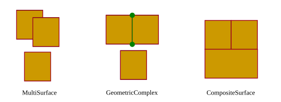
Fig. 2.1 Different types of aggregated geometries [GKNH2012]
The modelling of two-dimensional and three-dimensional geometry types is handled in a simplified way. All surface-based geometries are stored as polygons, which are aggregated to MultiSurfaces, CompositeSurfaces, TriangulatedSurfaces, Solids, MultiSolids, as well as CompositeSolids accordingly. This simplification substitutes the more complex representation used for those GML geometry classes in grey blocks in Fig. 2.2. Mapping the UML diagram to the relational schema now requires only one table (SURFACE_GEOMETRY), which is explained in Section 2.7.3.3.
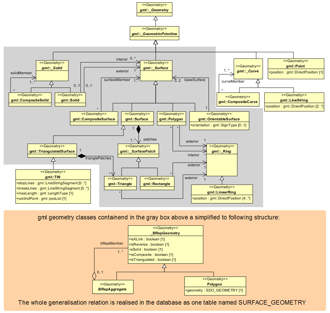
Fig. 2.2 Geometrical-topographical model. For simplification the geometry classes in the grey block are substituted by the construct in the orange block
In order to implement topology, CityGML uses the XML concept of XLinks provided by GML. Each geometry object that should be shared by different geometric aggregates or different thematic features is assigned a unique identifier, which may be referenced by a GML geometry property using a href attribute. The XLink topology is simple and flexible and nearly as powerful as the explicit GML3 topology model. However, a disadvantage of the XLink topology is that navigation between topologically connected objects can only be performed in one direction (from an aggregate to its components), not (immediately) bidirectional, as it is the case for GML’s built-in topology.