3.1.4. Appearance model
Information about a surface’s appearance, i.e. observable properties of the surface, is considered an integral part of virtual 3D city models in addition to semantics and geometry. Appearance relates to any surface-based theme, e.g. infrared radiation or noise pollution, not just visual properties and can be represented by – among others – textures and georeferenced textures. Appearances are supported for an arbitrary number of themes per city model. Each LoD of a feature can have individual appearances. Each city object or city model respectively may store its own appearance data. Therefore, the base CityGML classes _CityObject and CityModel contain a relation appearance and appearanceMember respectively.
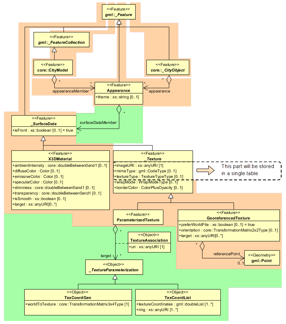
Fig. 3.5 Appearance model
Themes are represented by an identifier only. The appearance of a city model for a given theme is defined by a set of objects of class Appearance, referencing this theme through the attribute theme. All appearance objects belonging to the same theme compose a virtual group. An Appearance object collects surface data relevant for a specific theme through the relation surfaceDataMember. Surface data is represented by objects of the abstract class _SurfaceData. Its only attribute is the Boolean flag isFront, which determines the side (front and back face of the surface) a surface data object applies to.
A constant surface property is modelled as material. A surface property, which depends on the location within the surface, is modelled as texture. Each surface object can have both a material and a texture per theme and side. This allows for providing both a constant approximation and a complex measurement of a surface’s property simultaneously. If a surface object is to receive multiple textures or materials, each texture or material requires a separate theme. The mixing of themes or their usage is not explicitly defined but left to the application.
Materials define light reflection properties being constant for a whole surface object. The definition of the class X3DMaterial is adopted from the X3D and COLLADA specification (cf. X3D, COLLADA specification):
diffuseColor defines the colour of diffusely reflected light.
specularColor defines the colour of a directed reflection.
emissiveColor is the colour of light generated by the surface.
All colours use RGB values with red, green, and blue chanels, each defined as value between 0 and 1. Transparency is stored separately using the transparency element where 0 stands for fully opaque and 1 for fully transparent. ambientIntensity specifies the minimum percentage of diffuseColor that is visible regardless of light sources. shininess controls the sharpness of the specular highlight. 0 produces a soft glow while 1 results in a sharp highlight. isSmooth gives a hint for normal interpolation. If this Boolean flag is set to true, vertex normals should be used for shading (Gouraud shading). Otherwise, normals should be constant for a surface patch (flat shading). Target surfaces are specified using target elements. Each element contains the URI of one target surface geometry object.
The base class for textures is _AbstractTexture. Here, textures are always raster-based 2D textures. The raster image is specified by imageURI using a URI and may contain an arbitrary image data resource, even a preformatted request for a web service. The image data format can be defined using standard MIME types in the mimeType element. Textures can be qualified by the attribute textureType, differentiating between textures, which are specific for a certain object (specific) and prototypic textures being typical for that object surface (typical). Textures may also be classified as unknown. The specification of texture wrapping is adopted from the COLLADA standard. Possible values of the attribute wrapMode are none, wrap, mirror, clamp and border.
_AbstractTexture is further specialised according to the texture parameterisation, i.e. the mapping function from a location on the surface to a location in the texture image. Texture parameterisation uses the notion of texture space, where the texture image always occupies of the region [0,1]² regardless of the actual image size or aspect ratio. The lower left image corner is located at the origin. To receive textures, the mapping function must be known for each surface object.
The class GeoreferencedTexture describes a texture that uses a planimetric projection. Such a texture has a unique mapping function which is usually provided with the image file (e.g. georeferenced TIFF) or as a separate ESRI world file. The search order for an external georeference is determined by the Boolean flag preferWorldFile. Alternatively, inline specification of a georeference similar to a world file is possible. This internal georeference specification always takes precedence over any external georeference. referencePoint defines the location of the centre of the upper left image pixel in world space and corresponds to values 5 and 6 in an ESRI world file. Since GeoreferencedTexture uses a planimetric projection, referencePoint is two-dimensional and the orientation defines the rotation and scaling of the image in form of a 2x2 matrix (a list of 4 doubles in row-major order corresponding to values 1, 3, 2, and 4 in an ESRI world file). The CRS of this transformation is identical to the referencePoint’s CRS. If neither an internal nor an external georeference is given, the GeoreferencedTexture is invalid. Target surfaces are specified using target elements. Each element contains the URI of one target surface geometry object. All target surface objects share the mapping function defined by the georeference.
The class ParameterizedTexture describes a texture with a target-dependent mapping function. Each target surface geometry object is specified as URI in the uri attribute of a separate target element. The mapping is defined by associated classes of _TextureParameterization:
TexCoordList for the concept of texture coordinates, defining an explicit mapping of a surface’s boundary points to points in texture space, and
TexCoordGen when using a common 3x4 transformation matrix from world space to texture space, specified by the attribute worldToTexture.