3.1.3. Geometry model
Spatial properties of features are represented in CityGML using GML3’s geometry model, which is based on the ISO 19107 standard Spatial Schema [Herr2001] and represents 3D geometry according to the well-known Boundary Representation (B-Rep, cf. [FVFH1995]). Actually only a subset of the GML3 geometry package is used in CityGML. In addition, GML3’s explicit Boundary Representation is extended by a implicit geometry representation, which allows to define and reuse template geometries.
3.1.3.1. Geometric-topological model
The geometry model of CityGML consists of primitives, which may be combined to form complexes, composite geometries or aggregates. A zero-dimensional object is modelled as a Point, a one-dimensional as a _Curve. A curve is restricted to be a straight line, thus only the GML3 class LineString is used.
Combined geometries can be aggregates, complexes or composites of primitives (see illustration in Fig. 3.2). In an Aggregate, the spatial relationship between components is not restricted. They may be disjoint, overlapping, touching, or disconnected. GML3 provides a special aggregate for each dimension, a MultiPoint, a MultiCurve, a MultiSurface or a MultiSolid. In contrast to aggregates, a Complex is topologically structured: its parts must be disjoint, must not overlap and are allowed to touch, at most, at their boundaries or share parts of their boundaries. A Composite is a special complex provided by GML3. It can only contain elements of the same dimension. Its elements must be disjoint as well, but they must be topologically connected along their boundaries. A Composite can be a CompositeSolid, a CompositeSurface, or CompositeCurve and must be homeomorphic to the corresponding primitive geometry.
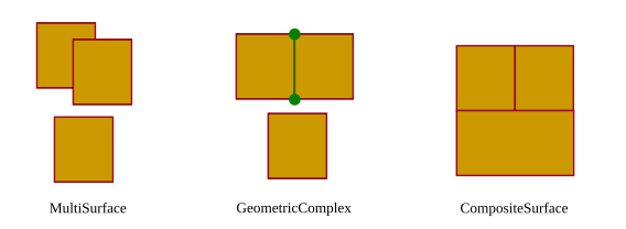
Fig. 3.2 Different types of aggregated geometries [GKNH2012]
The modelling of two-dimensional and three-dimensional geometry types in the 3DCityDB is handled in a simplified way. All surface-based geometries are stored as polygons, which are aggregated to MultiSurfaces, CompositeSurfaces, TriangulatedSurfaces, Solids, MultiSolids, as well as CompositeSolids accordingly. This simplification substitutes the more complex representations used for the GML geometry classes in the grey block of Fig. 3.3 with the elements in the orange block. This way, mapping surface-based geometries to the relational schema can be done with a single table (called SURFACE_GEOMETRY, see Section 3.2.3 for a detailed description).
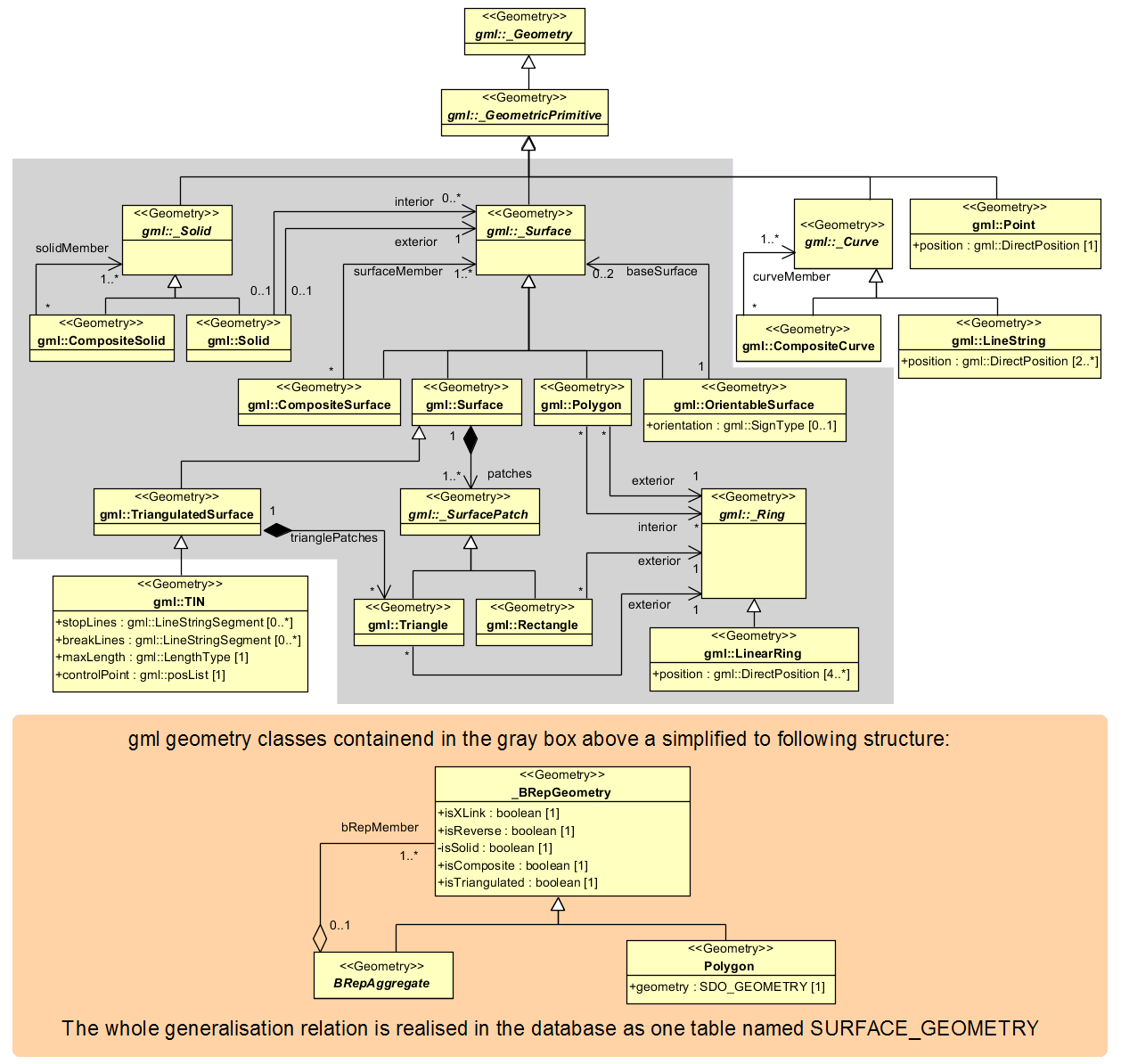
Fig. 3.3 Geometric-topological model. For simplification the geometry classes in the grey block are substituted by the construct in the orange block
Another reason for the explicit surface-based storage is that each surface can be assigned multiple appearances (e.g., textures) in CityGML and, thus, each appearance must be explicitly linkable to the corresponding polygons in the database (see also Section 3.1.4).
3.1.3.2. Implicit geometry
The concept of implicit geometries is an enhancement of the GML3 geometry model. An implicit geometry is a geometric object, where the shape is stored only once as a prototypical geometry. Examples are trees or other vegetation objects, traffic lights or traffic signs. This template geometry object is re-used or referenced many times, wherever the corresponding feature occurs in the 3D city model. Each occurrence is represented by a link to the prototypic shape geometry (in a local Cartesian coordinate system), by a transformation matrix that is multiplied with each 3D coordinate of the prototype, and by an anchor point denoting the base point of the object in the world coordinate reference system. The concept of implicit geometries is similar to the well-known concept of primitive instancing used for the representation of scene graphs in the field of computer graphics [FVFH1995].
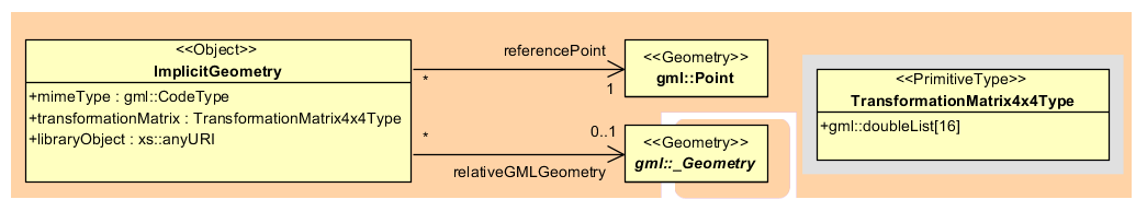
Fig. 3.4 Implicit geometry model
Implicit geometries may be applied to features from different thematic fields in order to geometrically represent the features within a specific level of detail (LOD). Thus, each CityGML thematic extension module (like Building, Bridge, and Tunnel etc.) may define spatial properties providing implicit geometries for its thematic classes.
The shape of an implicit geometry can be represented in an external file with a proprietary format, e.g. a VRML file, a DXF file, or a 3D Studio MAX file. The reference to the implicit geometry can be specified by an URI pointing to a local or remote file, or even to an appropriate web service. Alternatively, a GML3 geometry object can define the shape. This has the advantage that it can be stored or exchanged inline within the CityGML dataset. Typically, the shape of the geometry is defined in a local coordinate system where the origin lies within or near to the object’s extent. If the shape is referenced by an URI, also the MIME type of the denoted object has to be specified (e.g. “model/vrml” for VRML models or “model/x3d+xml” for X3D models).
The implicit representation of 3D object geometry has some advantages compared to the explicit modelling, which represents the objects using absolute world coordinates. It is more space-efficient, and thus more extensive scenes can be stored or handled by a system. The visualization is accelerated since 3D graphics hardware supports the scene graph concept. Furthermore, the usage of different shape versions of objects is facilitated, e.g. different seasons, since only the library objects have to be exchanged.