3.1.10. Digital terrain model
CityGML includes a very adaptable digital terrain model (DTM) which permits the combination of heterogeneous DTM types (grid, TIN, break lines, mass points) available in different levels of detail.
A DTM fitting to a certain city model is represented by the class ReliefFeature. This is a CityObject having the LoD step that fits the DTM as attribute. A relief consists of several ReliefComponents. Each of these components that are likewise CityObjects also comprises a LoD step. Individual geometrical types of the components are defined by the four subclasses of ReliefComponent: breaklines, triangular networks (TINs), mass points, and grids (raster). Geometrically, the corresponding ISO 19107 or GML classes define these types: breaklines by a single MultiCurve, TINs by TriangulatedSurfaces, mass points by MultiPoint, and raster by RectifiedGridCoverage.
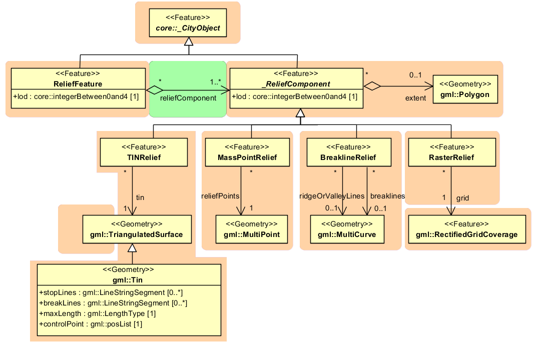
Fig. 3.16 UML diagram representing the digital terrain model
A relief can contain ReliefComponents of heterogeneous type and different LoDs. A relief in LoD2, for example, can contain some LoD3-TIN-ReliefComponents beside a LoD2-Raster-ReliefComponent. In some cases even a LoD1 grid may exist in some regions of the relief.
In order to geometrically separate the individual components of a grid, which can exist in different LoD, the validity polygon of a component (extent) is used. This polygon defines the scope in which the component is valid. A grid with three components is shown in Fig. 3.17. It depicts a coarse raster containing two high-resolution TINs (TIN 1 and 2). The validity polygon of the raster is represented by the blue line, while the validity polygons of the TINs are bordered in green and red. In this case, the validity polygon of the raster (grid) has two holes where the raster (grid) is not valid, although it does exist. Instead, the high-resolution TINs are used for the representation of the terrain in these regions. That means the validity polygons of the TINs exactly fit the two holes in the validity polygon of the raster (grid).
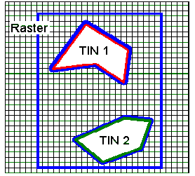
Fig. 3.17 A relief, consisting of three components and its validity polygons (from: [PGKS2005])
In the simplest and most frequent case, the validity polygon of a grid corresponds exactly with its bounding box, i.e. the spatial extent of the grid.