3.2. Database connections and operations
The Database tab of the operations window shown in the figure below allows a user to manage and establish database connections [1] and to execute database operations [2].
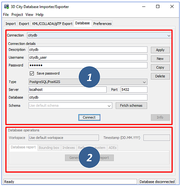
Fig. 3.2 Database tab.
3.2.1. Managing and establishing database connections
In order to connect to an instance of the 3D City Database, valid connection parameters must be provided on the Database tab.
Mandatory database connection details comprise the username and password of the database user, the type of the database, the server name (network name or IP address) and port number (default: 1521 for Oracle; 5432 for PostgreSQL) of the database server, and the database name (when using Oracle, enter the database SID or service name here). The optional schema parameter lets you define the database schema you want to connect to. Leave it empty to connect to the default schema. More information on how to work with multiple 3DCityDB schemas can be found in Section 2.9. If you need assistance, ask your database administrator for connection details and schemas. For convenience, a user can choose to save the password in the config file of the Importer/Exporter. Please be aware that the password will be stored as plain text.
To manage more than one database connection, connection details are assigned a short description text. The drop-down list at the top of the Database tab allows a user to switch between connections based on their description. By using the Apply, New, Copy and Delete buttons, edits to the parameters of the currently selected connection can be saved, a new connection with empty connections details can be created, and existing connections can be copied or deleted from the list.
The Connect / Disconnect button lets a user connect to / disconnect from a 3D City Database instance based on the provided connection details.
Note
With this version of the Importer/Exporter, you will be able to connect to version 4.0 to 3.0 instances of the 3D City Database but not to any previous version. See Section 1.4 for a guide on how to migrate a version 2 and 3 instances of the 3D City Database to the latest version 4.0.
The console window logs all messages that occur during the connection attempt. In case a connection could not be established, error messages are displayed that help to identify the cause of the connection problem. Otherwise, the console window contains information about the connected 3D City Database instance like those shown in Fig. 3.3. This information comprises the version of the 3D City Database, the name and version of the underlying database system, the connection string, the schema name, the spatial reference system ID (SRID) as well as its name and GML encoding (as specified during the setup of the 3D City Database), and whether the database tables are version-enabled.
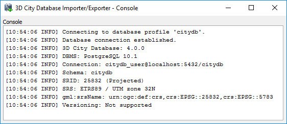
Fig. 3.3 Log messages for a successful database connection.
This information can be requested from a connected 3D City Database at any time using the Info button on the Database tab. Upon successful connection, the description of the active connection is moreover displayed in the title bar of the application window.
3.2.2. Executing database operations
After having established a connection to an instance of the 3D City Database, the Database tab (cf. [2] in Fig. 3.2) offers the following database operations to be executed on that instance:
- Generating a database report;
- Calculating/updating the bounding box of selected feature types;
- Managing indexes on database tables;
- Managing the spatial reference system of the database; and
- Displaying supported CityGML ADEs.
3.2.2.1. Generating a database report
A database report is a list of all tables of the 3D City Database together with their total number of rows. This operation therefore provides a quick overview of the contents of the 3D City Database. The report is printed to the console window.
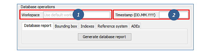
Fig. 3.4 Generating a database report.
If the database is version-enabled (Oracle only), the database report can be created for the contents of a specific workspace [1] at a given timestamp [2]. If no workspace is specified, the default LIVE workspace is chosen per default. If the workspace does not exist, a corresponding error message is provided.
Note
Workspaces are not a feature of the 3D City Database but are managed through the Oracle Workspace Manager tool. Please refer to the Oracle database documentation for details. Since PostgreSQL currently does not support workspaces, the corresponding input fields are disabled when connecting to a 3D City Database running on PostgreSQL.
3.2.2.2. Calculating/updating the bounding box
This dialog lets you calculate the 2D bounding box of the city objects stored in the database. The bounding box is useful, for instance, as input to spatial filters in CityGML imports and exports as well as KML/COLLADA/glTF exports (see documentation of the corresponding operations).
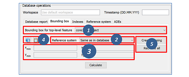
Fig. 3.5 Calculating the bounding box for selected feature types.
The coordinate values of the lower left (xmin, ymin) and upper
right (xmax, ymax) corner of the calculated bounding box are
rendered in the corresponding fields of the dialog [3]. The values are
also copied to the clipboard of your operating system and can therefore
easily be pasted into the import and export dialogs. You can also
manually copy the values to the clipboard by clicking the
 button [4], or by right-clicking on a data field [3] and choosing the
corresponding option from the context menu.
button [4], or by right-clicking on a data field [3] and choosing the
corresponding option from the context menu.
The calculation of the bounding box can be restricted to a specific city object type such as Building or WaterBody [1]. Similar to the generation of a database report, the user can request the bounding box for city objects living in a specific workspace at a given timestamp if the database is version-enabled (Oracle only). The coordinate values can optionally be transformed into a user-defined coordinate reference system that is available from the drop-down list [2]. Per default, the coordinate values are presented in the same reference system as specified for the 3D City Database instance during setup. See Section 2.8 for details on how to define and manage user-defined reference systems.
By using the map  button [4],
the calculated bounding box is rendered in a separate 2D map window
for visual inspection as shown below. The usage of this map window is
described in Section 3.7.
button [4],
the calculated bounding box is rendered in a separate 2D map window
for visual inspection as shown below. The usage of this map window is
described in Section 3.7.
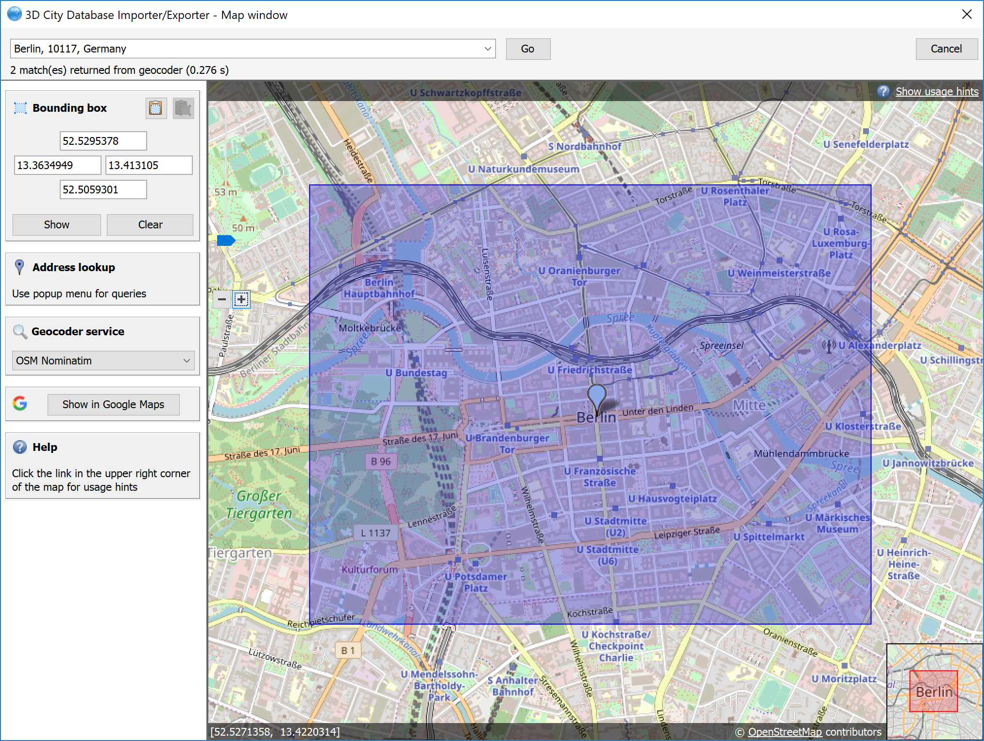
Fig. 3.6 Map window for displaying and choosing bounding boxes. Note that the coordinate values of the bounding box are shown in the upper left component.
The calculation of the bounding box is based on the values stored in the ENVELOPE column of the CITYOBJECT table. If this column is NULL or contains an incorrect value (e.g., in case the value could not correctly filled during import or the geometry representation of a city object has been changed), then the resulting bounding box will be wrong and subsequent operations might not provide the expected result. To fix the ENVELOPE values in the database, simply let the Importer/Exporter create missing values (i.e., replace NULL values) or recreate all values by clicking on the corresponding buttons [5]. This update process either affects only the city objects of a given feature type or all city objects based on the selection made in [1].
Note
This process directly updates the ENVELOPE column of the affected city objects and might take long to complete since the new values are calculated by evaluating all geometries of the city objects in all LoDs including implicit geometries.
3.2.2.3. Managing indexes
The Importer/Exporter allows the user to manually activate or deactivate indexes on predefined tables of the 3D City Database schema, and to check their status.
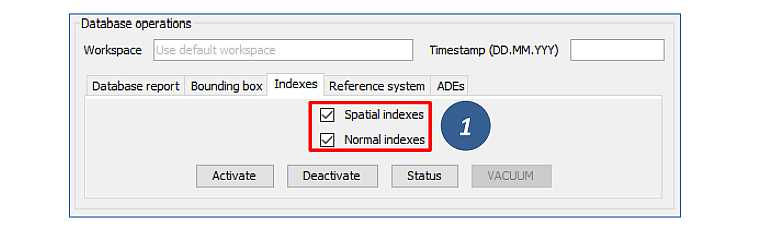
Fig. 3.7 Managing spatial and normal indexes.
The operation dialog differentiates between spatial indexes on geometry columns and normal indexes on columns with any other datatype [1]. The buttons Activate, Deactivate, and Status trigger a corresponding database process on spatial indexes only, normal indexes only or both index types depending on which checkboxes are selected [1]. Again, the user can define a workspace and timestamp on which the operation shall be executed if the database is version-enabled (Oracle only).
The index operations only affect the following subset of all indexes defined by the 3D City Database schema:
Index type
|
Column(s)
|
Table
|
Spatial
|
ENVELOPE
|
CITYOBJECT
|
Spatial
|
GEOMETRY
|
SURFACE_GEOMETRY
|
Spatial
|
SOLID_GEOMETRY
|
SURFACE_GEOMETRY
|
Normal
|
GMLID, GMLID_CODESPACE
|
CITYOBJECT
|
Normal
|
LINEAGE
|
CITYOBJECT
|
Normal
|
CREATION_DATE
|
CITYOBJECT
|
Normal
|
TERMINATION_DATE
|
CITYOBJECT
|
Normal
|
LAST_MODIFICATION_DATE
|
CITYOBJECT
|
Normal
|
GMLID, GMLID_CODESPACE
|
SURFACE_GEOMETRY
|
Normal
|
GMLID, GMLID_CODESPACE
|
APPEARANCE
|
Normal
|
THEME
|
APPEARANCE
|
Normal
|
GMLID, GMLID_CODESPACE
|
SURFACE_DATA
|
Normal
|
GMLID, GMLID_CODESPACE
|
ADDRESS
|
The result of an index operation is reported in the console window as shown below. For instance, Fig. 3.8 shows the result of a status query on both spatial and normal indexes. The status ON means that the corresponding index is enabled.
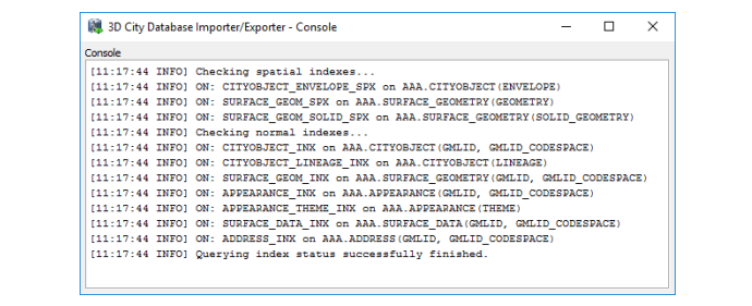
Fig. 3.8 Result of a status query on spatial and normal indexes.
Note
It is strongly recommended to deactivate the spatial indexes before running a CityGML import on a big amount of data and to reactive the spatial indexes afterwards. This way the import will typically be a lot faster than with spatial indexes enabled. The situation may be different when importing only a small dataset.
Warning
Activating and deactivating indexes can take a long time, especially if the database fill level is high. Note that the operation cannot be aborted by the user since this would result in an inconsistent database state.
3.2.2.4. Managing the spatial reference system of the database
When setting up a 3DCityDB instance, you have to choose a spatial reference system (SRS) by picking a spatial reference ID (SRID) supported by the database and a corresponding SRS name identifier (gml:srsName) that is used in CityGML exports (see and Section 1.3). These settings can be easily changed at any later time using the reference system operation.
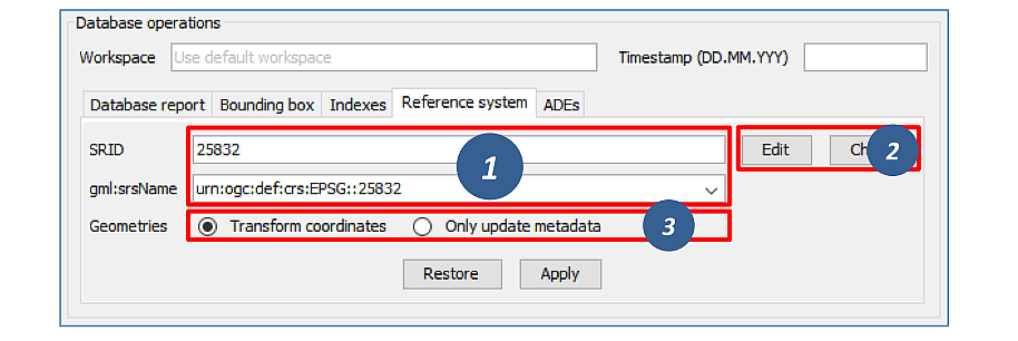
Fig. 3.9 Changing the SRS information of the 3DCityDB instance.
After connecting to a 3DCityDB, the SRID and gml:srsName input fields shown in the above dialog [1] are assigned the current values from the database. Simply edit the fields to pick a new SRID or SRS name identifier. Since changing the SRID potentially affects all geometries in your database and thus may take a long time to complete, the SRID field is disabled per default. Click on Edit [2] to enable changes to this field. Use the Check button [2] to make sure that your new SRID value is supported by the database. The gml:srsName field provides a drop-down list of common SRS identifier encoding schemes (such as OGC URN encoding, see Section 2.8). You may pick one of these proposals (be careful to replace the HEIGHT_SRID token with the correct value if required) or enter any other value.
When changing the SRID, you can choose whether the coordinates of geometry objects already stored in the database should be transformed to the new SRID or whether only the metadata should be updated [3]. The latter option might be enough, for example, if you accidentally picked a wrong SRID that does not match the imported geometries when setting up the database, and you simply want to correct this mistake.
Click on Apply to update the reference system information in the database according to your settings. The Restore button lets you discard any changes made to the SRID and gml:srsName fields.
Note
If you just want to use different gml:srsName values for different CityGML exports, then instead of changing the identifier in the database before every export it is simpler to create multiple user-defined reference systems for the same SRID (cf. Section 3.6.4) and pick one for each CityGML export (cf. Section 3.4).
3.2.2.5. Displaying supported CityGML ADEs
This tab provides a list of all CityGML Application Domain Extensions (ADEs) that are registered in the 3DCityDB instance and/or are supported by the Importer/Exporter. The following screenshot shows the corresponding dialog.
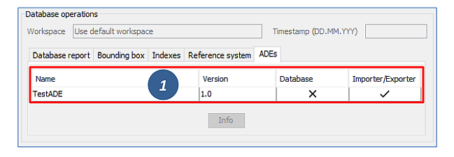
Fig. 3.10 Table of all supported CityGML ADEs.
The ADE table [1] contains one entry per CityGML ADE. Each entry lists the name and the version of the ADE and indicates whether it is supported by the database and/or the Importer/Exporter (using check or cross signs). Database support requires that the ADE has been successfully registered in the 3DCityDB instance using the ADE Manager Plugin (see Section 3.9.3). Additional support by the Importer/Exporter requires that a corresponding ADE extension has been copied into the ade-extensions folder within the installation directory of the Importer/Exporter. Only if both conditions are met both fields will contain a check sign. If no ADE has been detected upon database connection, the table remains empty.
In the example of Fig. 3.10, there is only an Importer/Exporter extension for an ADE called TestADE but the connected 3DCityDB instance lacks support for it. TestADE data would therefore not be handled by the Importer/Exporter and thus not stored into the database in this scenario.
If you select an entry in the ADE table and click the Info button (or simply double-click on the entry), metadata about the ADE will be displayed in a separate window as shown below. The Status field shows whether the ADE is fully supported, or some user action is required.
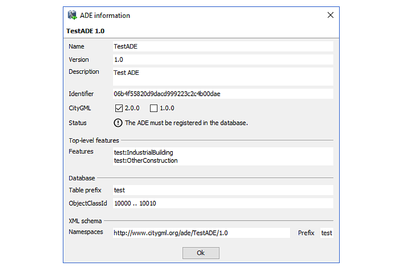
Fig. 3.11 ADE metadata dialog.