3.5. Exporting to KML/COLLADA/glTF
3D City Database contents can be directly exported in KML [Wils2008], COLLADA [BaFi2008], and glTF [Khro2018] formats for presentation, viewing, and visual inspection in a broad range of applications such as Earth browsers like Google Earth, ArcGIS Explorer, and Cesium etc.
Note
KML/COLLADA/glTF formatted exports come straight from the 3D City Database. No direct file transformation CityGML KML/COLLADA/glTF is supported yet. If a CityGML file shall be converted to KML/COLLADA/glTF, the CityGML content must be imported into the database first and then exported into the KML/COLLADA/glTF format.
The KML/COLLADA/glTF Export tab shown in Fig. 3.17 collects all parameters required for the export in a similar fashion as for a CityGML export (see the previous chapter). In addition, more fine-grained preference settings affecting the KML/COLLADA/glTF export are available on the Preferences tab of the operations window. Make sure to check these settings before starting the export process. A full documentation of the export preferences is available in Section 3.6.3. The following table provides a brief summary overview.
Preference name
|
Description
|
General Preference
|
Some common settings of the exported files
|
Rendering Preferences
|
Defines the look of the KML/COLLADA/glTF exports when visualized in the
virtual globes (e.g. Cesium, Google Earth, NASA World Wind, ESRI ArcGlobe).
Each of the top-level feature categories has its own Rendering settings here
|
Information Balloon
Preferences
|
KML offers the possibility of enriching its placemark elements with
information bubbles, so-called balloons. They can be specified here
|
Altitude/Terrain
Preferences
|
Controls the way through which the exported datasets to be
perfectly displayed in the Earth browser
|
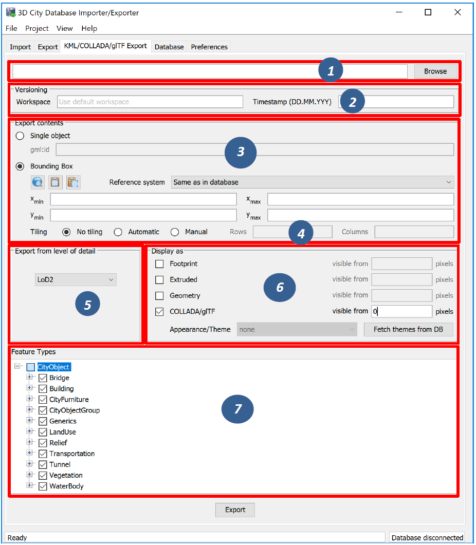
Fig. 3.17 The KML/COLLADA/glTF Export tab allowing for exporting KML/COLLADA/glTF models from the 3DCityDB
Output file selection. Type the filename directly into the text field or activate the file dialog provided by the operating system after pushing the Browse button [1].
Workspace selection. If the 3D City Database instance is version-enabled (Oracle only), the name of the workspace and the timestamp from which the data shall be exported can be specified [2]. If no workspace is provided, the default workspace is assumed (Oracle: LIVE).
Export contents. These KML/COLLADA/glTF Exporter allows for specifying/selecting the objects of interest for the export. These can be single objects or whole areas delimited by a bounding box. Two radio buttons [3] at the left side of the export dialog let you choose between those two options.
- Single object: Enter the GML IDs of the object(s) of interest. Multiple IDs have to be separated by commas.
- Bounding Box: Enter the coordinates of a bounding box defining the area of interest. Objects are exported if their centroids lie within the specified bounding box. The reference system used for defining the bounding box can be the same as the one used in the database or any other one supported by Oracle and PostGIS. It is also possible to add further user-defined reference systems (see the previous chapter). New reference systems can be added to the Import/Export tool (preferences tab, node Database, subnode Reference systems) if they are supported by the used database server. The target system with the same dimensionality (WGS84 for 2D, WGS84 3D for 3D) will be applied for the coordinate transformation during the KML/COLLADA/glTF Export.
Tiling only applies to exports of areas defined by a bounding box. Tiled exports are used in order to load and unload parts of the exported model depending on their current visibility when viewed, for example, in Google Earth. Since the Earth Browser’s responsiveness decreases greatly with single files larger than 10 Mb, tiled exports (with tile file sizes usually a lot smaller than that) are highly recommended. As mentioned above, only objects whose centroids lie within the tile’s bounding box will be exported.
There are three tiling modes [4] available for a KML/COLLADA/glTF export:
- no tiling: as the name implies, no tiling takes place. Just a single tile holding all the exported objects is exported. This is only advisable when the resulting file is at most 10 MB in size.
- automatic: the area enclosed by the bounding box will be exported in tiles having roughly the side length set on the preferences tab under the node KML/COLLADA/glTF Export, subnode Rendering (default value is 125m.). The amount of exported rows and columns will be calculated by dividing the length and width (in unit of meters) of the delimiting bounding box by the preferred tile side length and rounding up the result. For example: if the user wants to export a 1000m x 1100m bounding box with a preferred tile side length of 300m, 4x4 tiles will be generated since 1000/300 = 3.333 and 1100/300 = 3.666. This also implies: in case of automatic tiling it cannot be guaranteed that tiles will be perfectly square, but they will tend to.
- manual: the number of rows and columns can be freely set by the user. The area will be divided in equally spaced portions horizontally and vertically in WGS84 and the resulting tile sizes and forms will adapt to the values specified.
The exported tiles are organized with a hierarchical directory structure which means that each individual tile file is named by its column number and all the tile files that belongs to the same row are stored in a separate subfolder named by their corresponding row number. The numbering of both rows and columns should start with 0. All those subfolders are in turn stored in a folder named “Tiles”. This hierarchical directory structure (cf. Fig. 3.18) ensures that the exported tile files are distributed over different subfolders in order to avoid putting all tile files into a single folder which may result in significant performance issues at least under MS Windows operating systems.
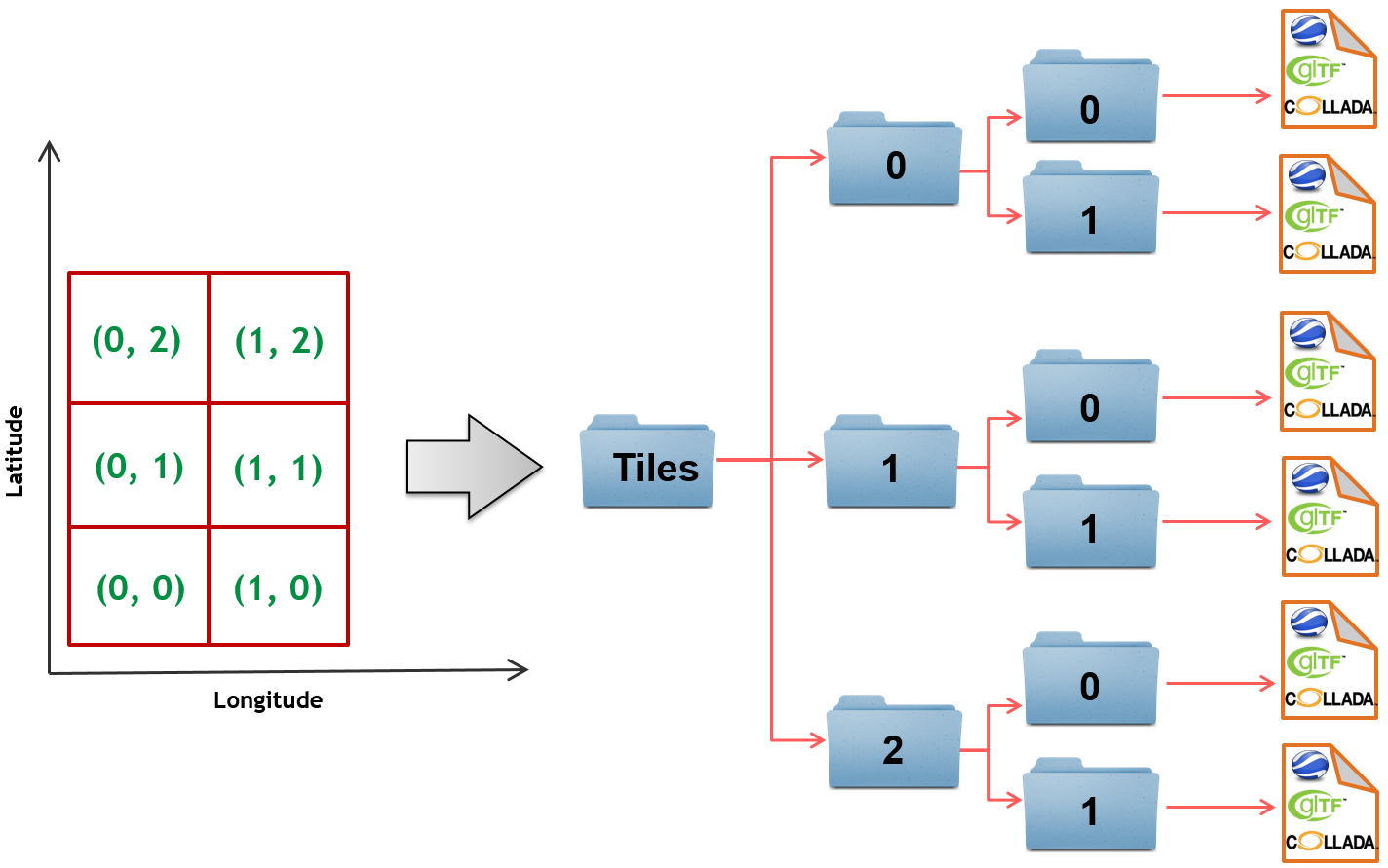
Fig. 3.18 Example: hierarchical directory structure for export of 2x3 tiles
Export from level of detail. The Level of Detail as defined by the CityGML specification should be used as basis information for the KML/COLLADA/glTF export. For the same city object higher levels of detail usually contain many more geometries and these geometries are more complex than in lower levels. For instance, a building made of 40 polygons in LoD2 may consist of 3000 polygons in LoD3. This means LoD3 based exports are a lot more detailed than LoD2 based exports, but they also take longer to generate, are bigger in size and therefore load more slowly in the Earth browser.
By using the drop-down list [5] a single constant LoD can be used as basis for all exports or it can be left to the Importer/Exporter to automatically determine which the highest LoD available for each cityobject is and then use it as the basis for the KML/COLLADA/glTF exports.
Display as. These fields in the export dialog [6] determines what will be shown when visualizing the exported dataset in earth browsers.
- Footprint: objects are represented by their ground surface projected onto the earth surface. This is a pure KML export.
- Extruded: objects are represented as blocks models by extruding their footprint to their height (calculated by using their 3D envelopes). This is a pure KML export.
- Geometry: objects are represented with fully detailed geometry information with respect to the selected Level of Detail. It can explicitly show the different thematic surfaces (e.g. wall and roof surfaces) by means of coloring them (textures are not supported by KML) according to the settings in the preferences tab (KML/COLLADA/glTF Export node, Rendering subnode). If not explicitly modeled, thematic surfaces will be inferred for LoD1 or LoD2 based exports following a trivial logic (surfaces touching the ground – that is, having a lowest z-coordinate- will be considered wall surfaces, all other will be considered roof surfaces), in LoD3 or LoD4 based exports surfaces not thematically modeled will be colored as wall surfaces.
- COLLADA/glTF: shows the detailed geometry in COLLADA and glTF formats including support for textures. The Appearance/Theme combo box below allows choosing from all possible appearance themes (as defined in the CityGML specification [GKNH2012]) available in the currently connected 3DCityDB instance. The list is workspace- and timestamp sensitive and will be filled on demand when clicking on the fetch button. Default value is none, which renders no textures at all and colors all surfaces according to the settings in the preference tab (KML/COLLADA/glTF Export node, Rendering subnode).
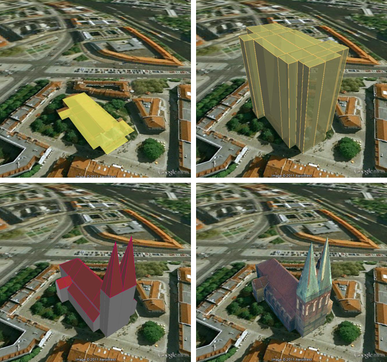
Fig. 3.19 Example: The same building displayed as (top down and left to right) footprint, extruded, geometry, COLLADA
Note
For Oracle, the Footprint and Extruded display forms
internally use the spatial function SDO_AGGR_UNION. This function is not
allowed to be used under Oracle 10g/11g with the Locator license
option even if it happens to be available. The Importer/Exporter does
not check the Oracle license option. Thus, it is up to the user to
observe the Oracle license and not to use the Footprint and Extruded
display forms under Oracle 10g/11g Locator. This restriction does not
hold for the Oracle Spatial license option. Likewise, starting from
Oracle 12c, SDO_AGGR_UNION is also available for Locator.
Depending on the chosen level of detail, some display form checkboxes will become enabled or disabled, depending on whether the level of detail offers enough information for this display form or not. For instance, Footprint can be exported from any CityGML LoD (0 to 4), whereas Extruded, Geometry, and COLLADA/glTF exports are possible from LoD1 upwards. Exports will have their filename enhanced with a suffix specifying the selected display form. This applies for both tiled and untiled exports.
With the visibility field next to each display form the user can control
the KML element <minLodPixels>, see [Wils2008]: measurement in screen
pixels that represents the minimum limit of the visibility range for a
given <Region>. A <Region> is in the generated tiled exports equivalent
to a tile. The <maxLodPixels> value is identical to the <minLodPixels>
of the next visible display form, so that display forms are seamlessly
switched when the viewer zooms in or out. The last visible display form
has a <maxLodPixels> value of -1, that is, visible to infinite size.
Visibility ranges can start at a value of 0 (they do not have to,
though). Please note that the region size in pixels depends on the
chosen tile size. Thus, if the tile size is reduced also the visibility
ranges should be reduced. Increases in steps of a third of the tile side
length are recommended. An example of a good combination for a tile size
of about 250m x 250m could be: Footprint, visible from 50 pixels,
Geometry, visible from 125 pixels, COLLADA/glTF, visible from 200
pixels. Some display forms, like Extruded in this example, can be
skipped. The visibility field only becomes enabled for bounding box
exports; single building exports are always visible.
Feature Types. Similar to CityGML imports and exports it is also possible to select what top-level feature types shall be displayed in a KML/COLLADA/glTF export. With the selection tree panel [7] it is possible to pick each category individually and also leave single categories out, i.e.: export CityFurniture and WaterBody only, or export everything but Building and so on. Between LoD1 and LoD4 all feature types are available. For LoD0 only those top-level feature types offering LoD0 geometry in the CityGML 2.0 schema (Building, Waterbody, LandUse, Transportation and GenericCityObject) are selectable, whereas the rest of the feature class checkboxes will become automatically disabled.
Note
Support for Relief features in KML/COLLADA/glTF exports is currently limited to the type TIN_RELIEF. Other Relief types such as MASSPOINT_RELIEF, BREAKLINE_RELIEF, and RASTER_RELIEF are not supported currently. Also, due to the usually wide-streched area of Relief features and the non-clipping nature of the BoundingBox filter it is recommended to export Relief features in a single step making use of the no tiling option and using an extensive enough BoundingBox. As an alternative, the digital terrain model data can be divided in smaller ReliefComponents tailored to match the tiling settings of the desired export (their area contained in or equal to the resulting tiles). This requires altering the original data nevertheless and, as such, it must be done before the CityGML contents are imported into the database at all.
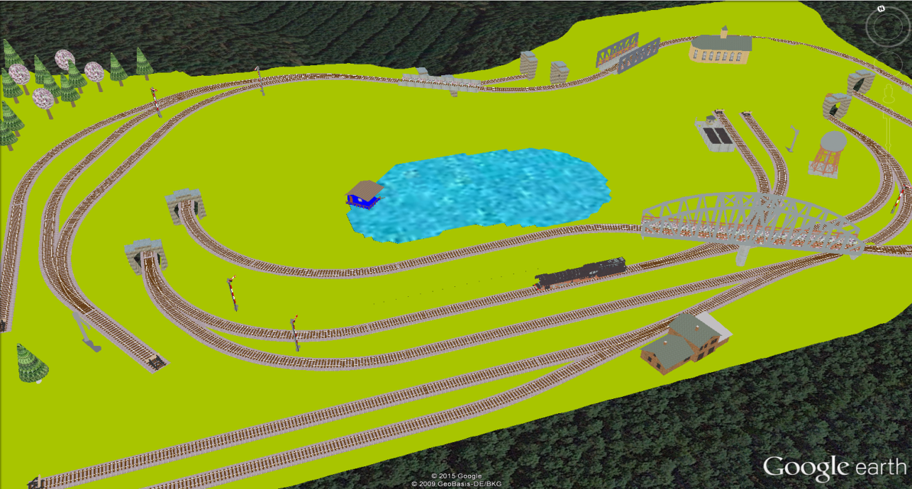
Fig. 3.20 Example for exported CityGML top-level features (building, bridge, tunnel, water, vegetation, transportation etc.) displayed as KML/COLLADA
KML/COLLADA/glTF export. Having completed all settings, the KML/COLLADA/glTF data export is triggered with the Export button at the bottom of the dialog (cf. Fig. 3.17). If a database connection has not been established manually beforehand, the currently selected entry on the Database tab is used to connect to the 3D City Database. Progress information is displayed within a separate status window. This status window also offers a Cancel button that lets a user abort the export process. The separate steps of the export process as well as possible error messages are reported to the console window.
After having completed the export, multiple files along with the Tiles
folder will be written to the prespecified output location. One of them
is called master KML file which contains a list of <NetworkLink>
elements pointing to every exported tile files stored in the Tiles
folder. This KML file can therefore be directly opened in Google Earth
for viewing and exploring the exported KML/COLLADA models. In addition,
for each selected display form (Footprint, Extruded, Geometry, and
COLLADA/glTF), a JSON formatted file called Master JSON file is
created and its contents should look like the following example:
Master JSON file example:
{
   "version": "1.0.0",
   "layername": "NYC_Buildings",
   "fileextension": ".kmz",
   "displayform": "extruded",
   "minLodPixels": 140,
   "maxLodPixels": -1,
   "colnum": 29,
   "rownum": 23,
   "bbox": {
      "xmin": -74.0209007,
      "xmax": -73.9707756,
      "ymin": 40.6996416,
      "ymax": 40.7295678
   }
}
As the name of each JSON parameter implies, this JSON file contains the relevant information about the specified export settings and can hence be seen as a kind of metadata allowing applications to interpret the contents of the exported datasets. For example, the length and width (in WGS84) of each tile can be determined using the following formulas:
\(TileWidth = (bbox.xmax – bbox.xmin) / colnum\)
\(TileLength = (bbox.ymax – bbox.ymin) / rownum\)
With these two calculated values, applications are also able to use the following formulas to rapidly retrieve the row and column number of the tile in which a given point lies:
\(ColumnNumber = floor ((X – bbox.xmin) / TileWidth)\)
\(RowNumber = floor ((Y – bbox.ymin) / TileLength)\)
where X and Y denote the WGS84 coordinates of the given point.
Further, if a bounding box is given, which is formed by a lower-left corner and an upper-right corner and their row and column numbers are expressed as (R1, C1) and (R2, C2) respectively, all those tiles that intersect with the given bounding box can be found iteratively, as their row and column numbers must fulfil the following conditions:
\(R1 \leq RowNumber \leq R2\) ∧ \(C1 \leq columnNumber \leq C2\).
3.5.1. Support of GenericCityObject having any geometry types
The earlier versions of KML/COLLADA/glTF Exporter have been designed to only support exports of surface-based geometries for all CityGML classes. Starting from version 3.0.0 of the 3DCityDB, the KML/COLLADA/glTF Exporter has been functionally enhanced with the support for exporting point and curve geometry types of GenricCityObject objects in KML/KMZ format. GenricCityObject is a feature class defined within the CityGML’s Generics module (see Section 2.6.4.5) that allows for modeling and exchanging of 3D city objects which are not covered by any other thematic modules of CityGML. The geometry of a GenericCityObject can be explicitly defined in LOD0-4 using arbitrary 3D GML geometry object (class gml:_Geometry). Thus, any complex structured objects that have point, line, surface, or solid geometries can be geometrically represented by means of GenricCityObject objects for every LOD. For example, the indoor routing network model, which are not defined in the current CityGML specification, could be even though modeled using the CityGML’s Generics module where each GenricCityObject object may represent a node or an edge of the network model.
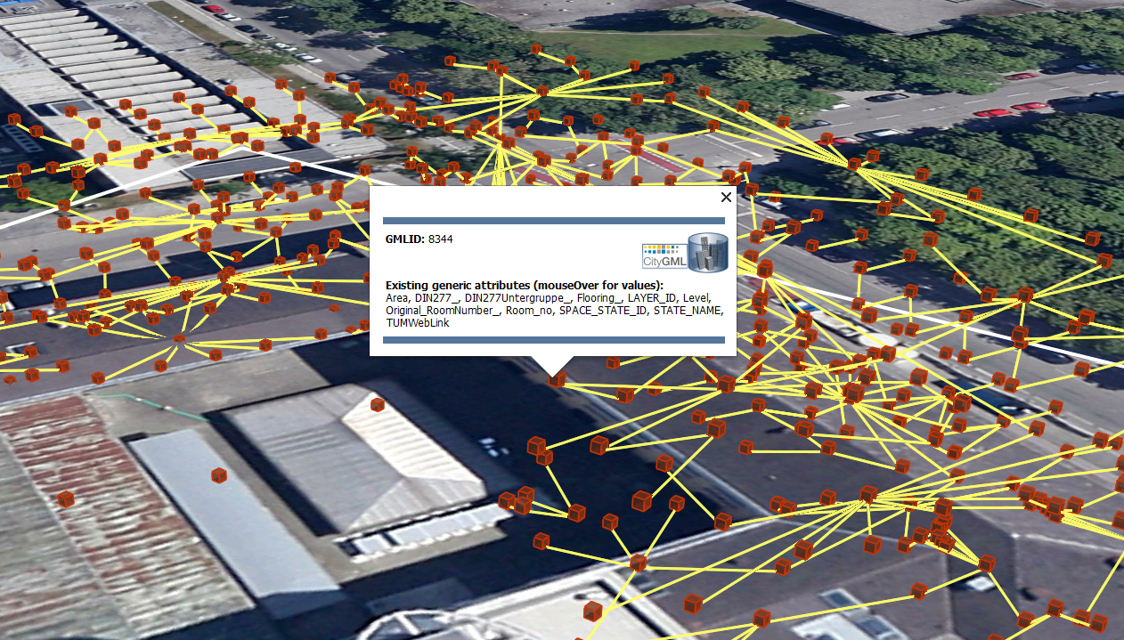
Fig. 3.21 Visualization of the network model of the building interior of Technical University Munich (TUM)
Depending on the chosen Level of Detail, the point and curve geometries of GenericCityObject objects are exported, along with their surface and solid geometries, into the output KML/KMZ file whose filename is enhanced with a suffix denoting the selected display form (e.g. Footprint, Extruded, Geometry, or COLLADA/glTF).
3.5.2. Loading exported models in Google Earth and Cesium Virtual Globe
In order to make full use of the features and functionalities provided by Google Earth, it is highly recommended to use the enhanced version of Google Earth – Google Earth Pro which is available free of charge starting from January 2015. Some of the features described in this documentation, like highlighting, can also flawlessly work in the normal Google Earth with version 6.0.1 or higher.
Displaying a file in Google Earth can be achieved by opening it through the menu (“File”, “Open”) or double-clicking on any kml or kmz file if these extensions are associated with the program (default option at Google Earth’s installation time).
Loaded files can be refreshed when generated again after loading (if for example the balloon template file was changed) by choosing the “Revert” option in the context menu on the sidebar. There is no need to delete and load them again or shutdown or restart the Earth browser.
For best performance, cache options (“Tools”, “Options”, “Cache”) should be set to their maximum values, 1024 MB for memory cache size, 2000 MB for disk cache. Actual maximums may be lower depending on the computer’s hardware.
Google Earth enables showing the terrain layer by default for realistic display of 3D models. Disabling of terrain layer is only possible in Google Earth Pro. You may need to disable the terrain layer in case that the exported models cannot be seen although shown as loaded in Google Earth’s sidebar, since they are probably buried into the ground (see Section 3.6.3.4).
When exporting balloons into individual files (one for each object) written together into a balloon directory access to local files and personal data must be allowed (“Tools”, “Options”, “General”). Google Earth will issue a security warning that must be accepted, otherwise the contents of the balloons (when in individual files and not as a part of the doc.kml file) will not be displayed.
It is also possible to upload the generated KML/COLLADA/glTF files to a web server and access them from there via internet browser with Cesium Virtual Globe (starting from December 2015, the Google Earth Plugin is no longer supported by most modern web browsers due to security considerations). In this case, the Cross Origin Resource Sharing (CORS) shall be enabled on the web server to allow cross-domain AJAX requests sent from the based-web frontend.
Note
Starting with version 7 (and at least up to version 7.1.1.1888) Google Earth has changed the way transparent or semi-transparent surfaces are rendered. This is especially relevant for visualizations containing highlighting surfaces (explained in Section 3.6.3.2). When viewing KML/COLLADA models in Google Earth it is strongly recommended to use Google Earth (Pro) version 7 or higher and switch to the OpenGL graphic mode for an optimal viewing experience. Changing the Graphic Mode can be achieved by clicking on Tools, Options entry, 3D View Tab.
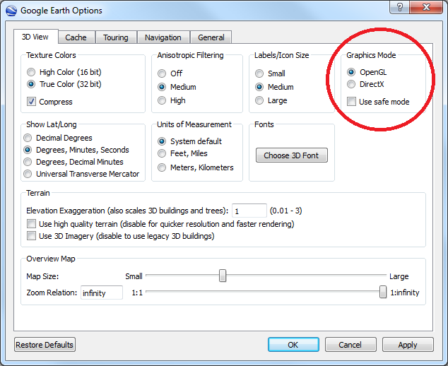
Fig. 3.22 Setting the Graphics Mode in Google Earth
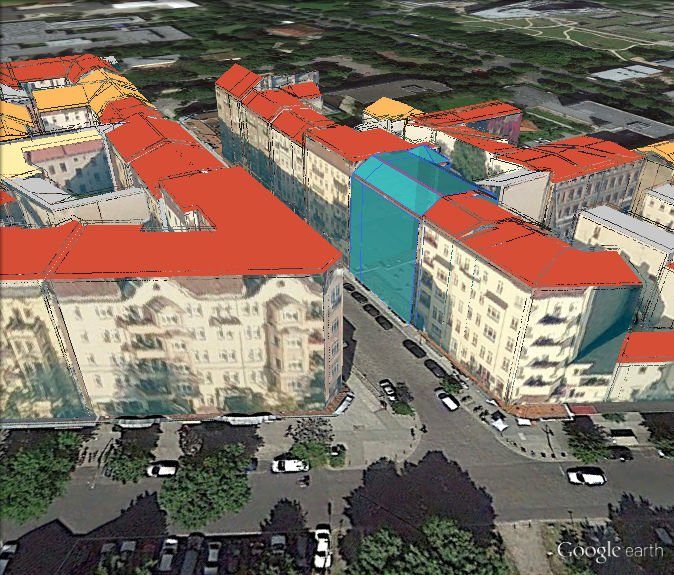
Fig. 3.23 KML/COLLADA models rendered with DirectX, highlighting surface borders are noticeable everywhere
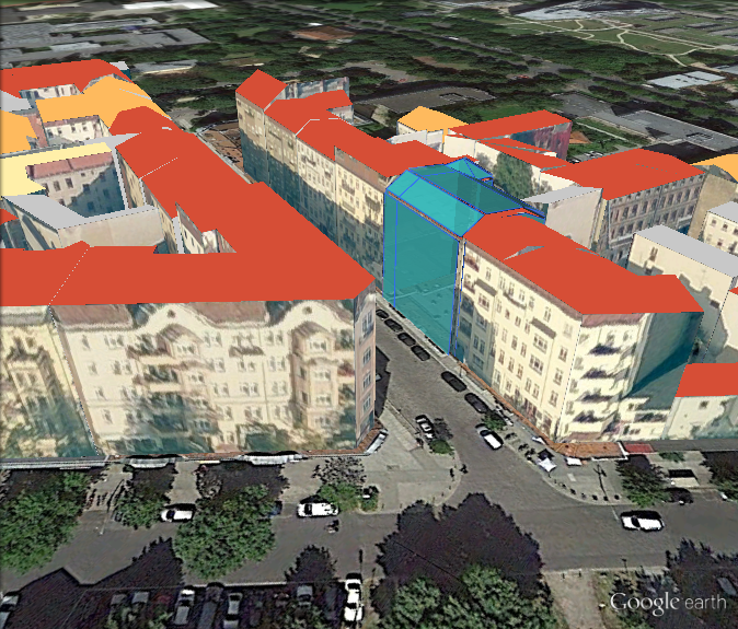
Fig. 3.24 The same scene rendered in OpenGL mode