3.6.3. KML/COLLADA/glTF export preferences
The preferences tab contains four subnodes – General, Rendering, Balloon, and Altitude/Terrain – make customization of these exports possible. These settings will be explained in the following sections in details.
3.6.3.1. General Preferences
Some common features of the exported files, especially those related to tiling options, can be set under the preferences tab, node KML/COLLADA/glTF Export, subnode General.
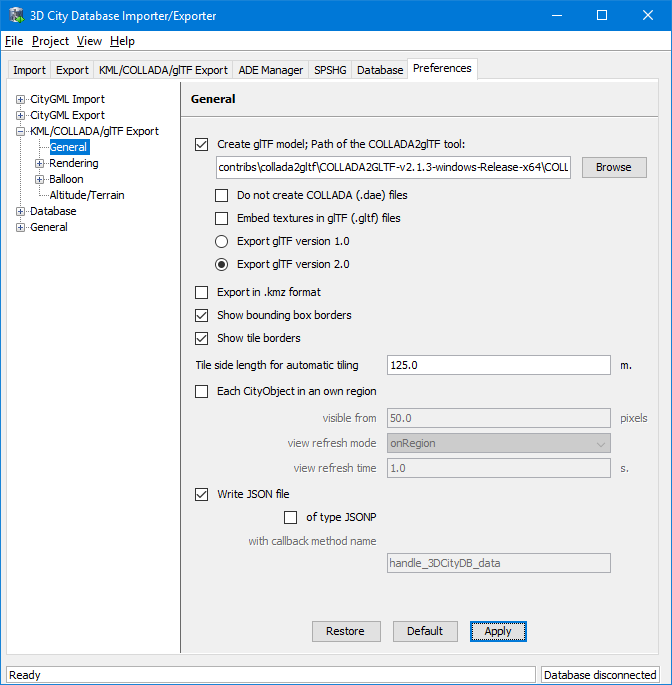
Fig. 3.45 General settings for the KML/COLLADA/glTF export
3.6.3.1.1. Create glTF model
In addition to COLLADA models, the Importer/Exporter can also create glTF models for efficient loading and rendering of 3D contents on WebGL-enabled web browsers. If the “Create glTF model” option is activated, the Importer/Exporter requires an open source tool called COLLADA2glTF to convert the exported COLLADA models to glTF models. The COLLADA2glTF tool is available for Windows, Linux, and Mac OS X and has been installed together with the Importer/Exporter and located in the subfolder contribs/collada2gltf of the installation directory. Per default, the relative path (depending on the operating system in use) of the COLLADA2glTF tool is proposed in the Path of the COLLADA2glTF tool text field whose value will be used by the Importer/Exporter to run the target executable file. Thus, if you want to use another version of the COLLADA2glTF tool, its absolute path has to be manually specified using, for example, the Browse button to open a file selection dialog. Starting with the Importer/Exporter version 4.0.0 however, version 2.1.0 or later of the COLLADA2glTF tool is required in order to enable support for both glTF version 1.0 and 2.0. The pre-installed COLLADA2glTF binaries come already in version 2.1.3. It is also possible to just export glTF models without COLLADA models by activating the Do not create COLLADA (.dae) files checkbox.
When exporting a textured city object in glTF, its texture images can either be encoded in the Base64 format and embedded into the glTF file, or saved as separate image files in the same directory as the glTF file having references to them. This can be controlled by the setting Embed textures in glTF (.gltf) files. In fact, both options have their pros and cons: the glTF file without embedded texture images allows client applications to realize an incremental loading effect which may give a better user experience, since the geometry contents and texture images can be loaded and rendered consecutively. However, this will result in a large amount of AJAX requests which might possibly impair the overall visualization performance especially when a large number of city objects are loaded simultaneously. This issue can be avoided by choosing the way of embedding the texture images into the glTF file. However, loading of the geometries and textures of a city object must be performed within one AJAX request that may slightly slow down the speed of the visualization of individual city object.
Note
The exported glTF file can be further converted to the so-called binary glTF file which is a binary container for glTF models and allows for faster loading and processing 3D objects. However, this conversion process is currently not yet supported by the KML/COLLADA/glTF Exporter and therefore needs to be carried out later using third party tools which can be found on the https://github.com/KhronosGroup/glTF website.
3.6.3.1.2. Export in kmz format
Determines in which format single files and tiled exports should be written: kmz when selected, kml when not. Whatever format is chosen, the main file (so called master file, pointing to all others) will always be a kml file, all other files will comply with this setting.
Tests have shown shorter loading times (in Google Earth) for the kml format (as opposed to kmz) when loading from the local hard disk. The Earth Browser’s stability also seems to improve when using the uncompressed format. On the other hand, when loading files from a server kmz reduces the amount of requests considerably, thus increasing performance. Kmz is also recommended for a better overview since kml exports may lead to a large number of directories and files.
The Export in kmz format and Create glTF model options are mutually exclusive. A warning message will be displayed when the user trys to choose the both.
3.6.3.1.3. Show bounding box borders
When exporting a region of interest via the bounding box option in the KML/COLLADA/glTF Export tab, this checkbox specifies whether the borders of the whole bounding box will be shown or not. The frame of the bounding box is four times thicker than the borders of any single tile in a tiled export.
3.6.3.1.4. Show tile borders
Specifies whether the borders of the single tiles in a tiled export will be shown or not.
3.6.3.1.5. Tile side length for automatic tiling
Applies only to automatically tiled exports and sets the approximate square size of the tiles. Since the Bounding Box settings in the KML/COLLADA/glTF Export tab are the determining factor for the area to be exported and have priority over this setting, the resulting tiles may not be perfectly square or have exactly the side length fed into this field.
3.6.3.1.6. Each CityObject in an own region
The visibility of the objects exported can be further fine-tuned by this option. While the visibility settings on the main KML/COLLADA/glTF Export tab apply to the whole area (no tiling) or to each tile (automatic, manual) being exported, this checkbox allows to individually define a KML <Region> for every single city object. The limits of the object’s region are those of the object’s CityGML Envelope.
Note
This setting only takes effect when if the export KML/KMZ files are opened with Google Earth (Pro). The Cesium-based 3D web client will silently ignore this setting.
Following the KML Specification [Wils2008], each KML <Region> is
defined inside a KML <NetworkLink> and has an associated KML <Link>
pointing to a file. This implies when this option is chosen a subfolder
is created for each object exported, identified by the object’s gmlId.
The object’s subfolder will contain any KML/COLLADA/glTF files needed
for the visualization of the object in the Earth browser. This folder
structure (which can contain a large number of subfolders) is required
for the KML <Region> visibility mechanism to work.
When active, the parameters affecting the visibility of the object’s KML
<Region> can be set through the following related fields.
The field visible from determines from which size on screen the
object’s KML <Region> becomes visible, regardless of the visibility
value of the containing tile, if any. Since this value is the same for
every single object and they have all different envelope sizes a good
average value should be chosen.
The field view refresh mode specifies how the KML <Link> corresponding
to the KML <Region> is refreshed when the geographic view changes. May
be one of the following:
- never - ignore changes in the geographic view.
- onRequest - refresh the content of the KML
<Region>only when the user explicitly requests it. - onStop - refresh the content of the KML
<Region>n seconds after movement stops, where n is specified in the field view refresh time. - onRegion - refresh the content of the KML
<Region>when it becomes active.
As stated above, the field view refresh time specifies how many
seconds after movement stops the content of the KML <Region> must be
refreshed. This field is only active and its value is only applied when
view refresh mode is onStop.
3.6.3.1.7. Write JSON file
After exporting some cityobjects in KML/COLLADA/glTF you may need to include them into websites or somehow embed them into HTML. When working with tiled exports referring to a specific object inside the KML/COLLADA/glTF files can become a hard task if the contents are loaded dynamically into the page. It is impossible to tell beforehand which tile contains which object. This problem can be solved by using a JSON file that is automatically generated when this checkbox is selected.
In the resulting JSON file each exported object is listed, identified by its gmlId acting as a key and some additional information is provided: the envelope coordinates in CRS WGS84 and the tile, identified by row and column, the object belongs to. For untiled exports the tile’s row and column values are constantly 0.
This JSON file has the same name as the so-called master file and is located in the same folder. Its contents can be used for indexed search of any object in the whole KML/COLLADA/glTF export.
{
   "BLDG_0003000b0013fe1f": {
      "envelope": [13.411962, 52.51966, 13.41277, 52.520091],
      "tile": [1, 1]
   },
   ...
   "BLDG_00030009007f8007": {
      "envelope": [13.406815, 52.51559, 13.40714, 52.51578],
      "tile": [0, 0]
   }
}
The JSON file can automatically be turned into JSONP (JSON with padding) by means of adding a function call around the JSON contents. JSONP provides a method to request data from a server in a different domain, something typically forbidden by web browsers since it is considered a cross-site-scripting attack (XSS). Thanks to this minimal addition, the JSON file contents can be more easily embedded into webpages or interpreted by web kits without breaking any rules. The function call name to be added to the original JSON contents is arbitrary and must only be entered in the callback method name field.
Note
Another solution for overcoming the restriction on making cross-domain requests is to make use of the Cross-Origin Resource Sharing (CORS) mechanism by enabling the web server to include additional HTTP headers in the response that allows web browsers to access the requested data. When working with the 3DCityDB-Web-Map-Client, it is required that the web server storing the KML/COLLADA/glTF datasets must be CORS-enabled. In this case, there is no need anymore to use this JSONP solution and the option of type JSONP should be deactivated.
3.6.3.2. Rendering Preferences
Most aspects regarding the look of the KML/COLLADA/glTF exports when visualized in virtual globes like Google Earth and Cesium can be customized under the preferences tab, node KML/COLLADA/glTF Export, subnode Rendering. Each of the top-level feature categories has its own Rendering settings. For the sake of clarity the most complex Rendering settings for Buildings will be explained here as an example. Settings for all other top-level features are either identical or simpler. An exceptional case is GenricCityObject which can be exported into point or line geometries, and the corresponding settings will be explained at the end of this section.
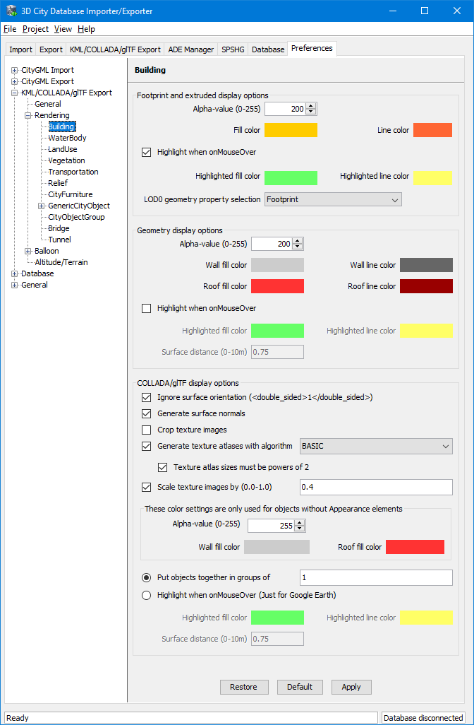
Fig. 3.46 Rendering settings for the KML/COLLADA/glTF Building export
All settings in this menu are grouped according to the display form they relate to.
3.6.3.2.1. Footprint and extruded display options
In this section the fill and line colors can be selected. Additionally, it can be chosen whether the displayed objects should be highlighted when being run over with the mouse or not. Highlighting colors can only be set when the highlighting option is enabled. The alpha value affects the transparency of all colors equally: 0 results in transparent (invisible) colors, 255 in completely opaque ones. A click on any color box opens a color choice dialog.
As defined in the CityGML specification [GKNH2012] CityGML version 2.0.0 allows LoD0 representation (footprint and roofprint representations) for buildings and building parts. If LoD0 in the Level of Export setting on the main KML/COLLADA/glTF Export tab is selected, there are three options available for LoD0 geometry export:
- footprint: the footprint geometries of the buildings or building parts will be exported
- roofprint: the roofprint geometries of the buildings or building parts will be exported
- roofprint, if none then footprint: footprint geometries will be exported if none of the roofprint geometries are found.
3.6.3.2.2. Geometry display options
This parameter section distinguishes between roof and wall surfaces and allows the user to color them independently. The alpha value affects the transparency of all roof and wall surface colors in the same manner as in the footprint and extruded cases: 0 results in transparent (invisible) colors, 255 in completely opaque ones. A click on any color box opens a color choice dialog.
As previously stated: when not explicitly modeled, thematic surfaces will be inferred for LoD1 or LoD2 based exports following a trivial logic (surfaces touching the ground –that is, having a lowest z-coordinate- will be considered wall surfaces, all other will be considered roof surfaces), in LoD3 or LoD4 based exports surfaces not thematically modeled will be colored as wall surfaces.
The highlighting effect when running with the mouse over the exported objects can also be switched on and off. Since the highlighting mechanism relies internally on a switch of the alpha values on the highlighting surfaces, the alpha value set in this section does not apply to the highlighted style of geometry exports, only to their normal style. For a detailed explanation of the highlighting mechanism see the following section.
3.6.3.2.3. COLLADA/glTF display options
These parameters control the export of COLLADA and glTF models. The first option addresses the fact that sometimes objects may contain wrongly oriented surfaces (points ordered clockwise instead of counter-clockwise) as a result of errors in some previous data gathering or conversion process. When rendered, wrongly oriented surfaces will only be textured on the inside and become transparent when viewed from the outside. Ignore surface orientation informs the viewer to disable back-face culling and render all polygons even if some are technically pointing away from the camera.
Note
This will result in lowered rendering performance. Correcting the surface orientation data is the recommended solution. This option only provides a quick fix for visualization purposes.
The activation of the option Generate surface normal allows calculating the surface normals for the exported object surfaces that can be illuminated with a shading effect in 3D scenes and therefore provides a better visual representation of the 3D object which has a constant color throughout its surfaces. If this option is not activated, this 3D object will be rendered as a solid geometry without any visual distinction of its boundary surfaces (cf. Fig. 3.47). However, when exporting textured 3D models, the shading effect is not relevant, since the texture information can already provide a sophisticated visual effect.
Note
Starting with version 4.0.0, the Importer/Exporter activates the option Generate surface normal by default for all (top-level) features if such information is available.
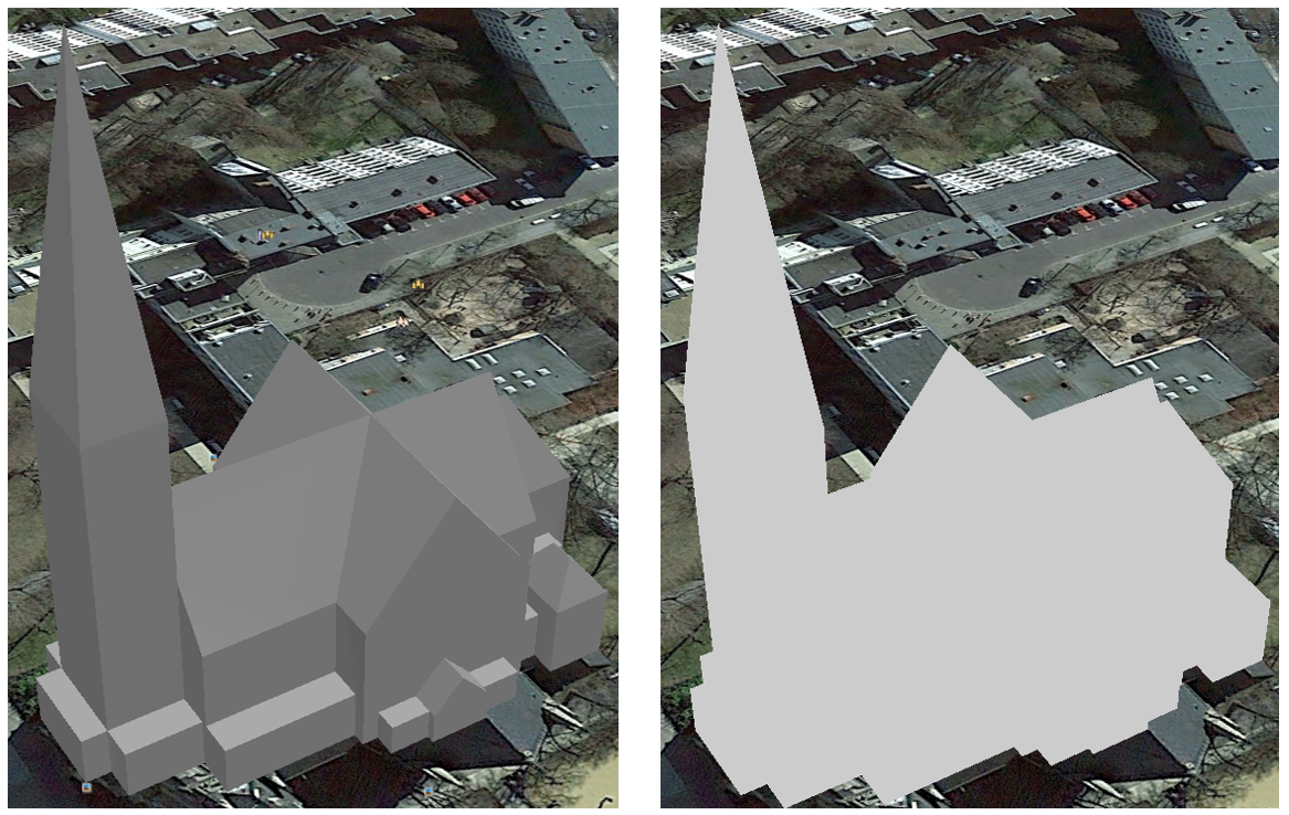
Fig. 3.47 Comparison of the different visual effects of the same 3D model with (the left figure) and without (the right figure) surface normals
Surface textures can be stored in an image file, or grouped into large canvases containing all images clustered together so-called texture atlases, which can significantly increase the storage efficiency and loading speed of 3D models. However, in some CityGML datasets, it might occur that a very large texture atlas image is shared by multiple surface geometries belonging to many different city objects. In this case, every exported COLLADA/glTF model representing a city object will receive a complete copy of the texture atlas image in which only a small portion of it is actually used. This will result in extreme performance issues when loading and rendering such COLLADA/glTF models in Earth browsers. In order to avoid this, the option Crop texture images shall be activated which allows cropping the large texture atlas image into a number of small texture images, each of which could be very small in size and should correspond to only one surface geometry of the city object.
With the option Generate texture atlases with algorithm, grouping images in an atlas or not and the algorithm selected for the texture atlas construction (differing in generation speed and canvas efficiency) can be set here. Depending on the algorithm and size of the original textures, an object can have one or more atlases, but atlases are not shared between separate objects.
The texture atlas algorithms address the problem of two-dimensional image packing, also known as ‘knapsack problem’ in different ways (see [CGJT1980]):
- BASIC: recursively divides the texture atlas into empty and filled regions (see http://www.blackpawn.com/texts/lightmaps/default.html). The first item is placed in the top left corner. The remaining empty region is split into two rectangles along the sides of the item. The next item is inserted into one of the free rectangles and the remaining empty space is split again. Doing this in a recursive way builds a binary tree representing the texture atlas. When adding an item, there is no information of the sizes of the items that are going to be packed after this one. This keeps the algorithm simple and fast. The items may be rotated when being inserted into the texture atlas.
- TPIM: touching perimeter (see [LoMV1999] and [LoMM2002]). Sorts images according to non-increasing area and orients them horizontally. One item is packed at a time. The first item packed is always placed in the bottom-left corner. Each following item is packed with its lower edge touching either the bottom of the atlas or the top edge of another item, and with its left edge touching either the left edge of the atlas or the right edge of another item. The choice of the packing position is done by evaluating a score, defined as the percentage of the item perimeter which touches the atlas borders and other items already packed. For each new item, the score is evaluated twice, for the two item orientations, and the highest value is selected.
- TPIM w/o image rotation: touching perimeter without rotation. Same as TPIM, but not allowing for rotation of the original images when packing. Score is evaluated only once since only one orientation is possible.
From the algorithms, BASIC is the fastest (shortest generation time) and produces good results, whereas TPIM is the most efficient (highest used area/total atlas size ratio).
Scaling texture images is another means of reducing file size and increasing loading speed. A scale factor of 0.2 to 0.5 often still offers a fairly good image quality while it has a major positive effect on these both issues. Default value is 1.0 (no scaling). This setting is independent from the atlas setting and both can be combined together. It is possible to generate atlases and then scale them to a smaller size for yet shorter loading times in Earth browsers.
In the next parameter section, the fill color of the roof and wall surfaces can be set by clicking on the corresponding color box to open the color selection dialog. The alpha value that affect the transparency of all surface colors can also be selected from a range of 0 (completely transparent) to 255 (completely opaque).
Note
This setting only takes effect if none of the appearance themes (as defined in the CityGML specification [GKNH2012]) is selected or available in the currently connected 3DCityDB instance.
Buildings can be put together in groups into a single model/placemark. This can also speed up loading, however it can lead to conflicts with the digital terrain model (DTM) of the Earth browser, since buildings grouped together have coordinates relative to the first building on the group (taken as the origin), not to the Earth browser’s DTM. Only the first building of the group is guaranteed to be correctly placed and grounded in the Earth browser. If the objects being grouped are too far apart this can result in buildings hovering over or sinking into the ground or cracks appearing between buildings that should go smoothly together.
Up to Google Earth 7, no highlighting of model placemarks loaded from a location other than Google Earth’s own servers is supported natively (glowing blue on mouse over). Therefore, a highlighting mechanism of its own was implemented in the KML/COLLADA/glTF exporter: highlighting is achieved by displaying a somewhat “exploded” version of the city object being highlighted around the original object itself. “Exploded” means all surfaces belonging to the object are moved outwards, displaced by a certain distance orthogonally to the original surface. This “exploded” highlighting surface is always present, but not always visible: when the mouse is not placed on any building (or rather, on the highlighting surface surrounding it closely) this “exploded” highlighting surface has a normal style with an alpha value of 1, invisible to the human eye. When the mouse is place on it, the style changes to highlighted, with an alpha value of 140 (hard-coded), becoming instantly visible, creating this model placemark highlighted feel. The displacement distance for the exploded highlighting surfaces can be set here. Default value is 0.75m.
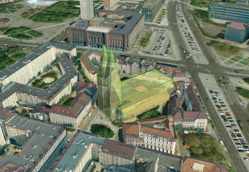
Fig. 3.48 Object exported in the COLLADA display form being highlighted on mouseOver
This highlighting mechanism only works in Google Earth and has an important side effect: the model’s polygons will be loaded and displayed twice (once for the representation itself, once for the highlighting), having a negative impact in the viewing performance of the Earth browser. The more complex the models are, the higher the impact is. This becomes particularly noticeable for models exported from a LoD3 basis upwards. The highlighting and grouping options are mutually exclusive.
3.6.3.2.4. GenericCityObject
As previously stated: in addition to the standard support for surface and solid geometry exports, other geometry types like point and line for the feature class GenricCityObject can also be exported in KML format. The related rendering node contains two further independent subnodes (“Surface and Solid” and “Point and Curve”) that allows for customizing the export of different geometry types individually. As the subnode “Surface and Solid” has similar settings illustrated in the previous section, only the settings within the subnode “Point and Curve” will be explained in the following paragraphs.
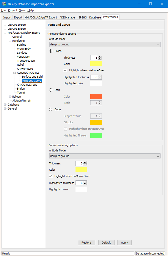
Fig. 3.49 Rendering settings for point and curve geometry exports for GenericCityObject
The field Altitude mode specifies how the Z-coordinates (altitude) of the exported point geometries are interpreted by the earth browser. Possible value may be one of the following options:
- absolute: the altitude is interpreted as an absolute height value in meters according to the vertical reference system (EGM96 geoid in KML).
- relative: the altitude is interpreted as a value in meters above the terrain. The absolute height value can be determined by adding the attitude to the elevation of the point.
- clamp to ground: the altitude will be ignored and the point geometry will be always clamp to the ground regardless of whether the terrain layer is activated or not.
Three setting options are available which allow user to choose a more appropriate display form for point geometry on the 3D map:
- Cross: The point geometry can be spatially represented by using a cross-line in the form like “X” with the length size of around 2 meters (hard-encoded). Changing the thickness and color settings will affect the width of the cross-line geometry in pixels and the display color respectively. The mouseOver highlighting effect is also supported and can be switched on and off by the user. When highlighting is enabled, further settings can be made for the thickness and color properties of the highlighting geometry.
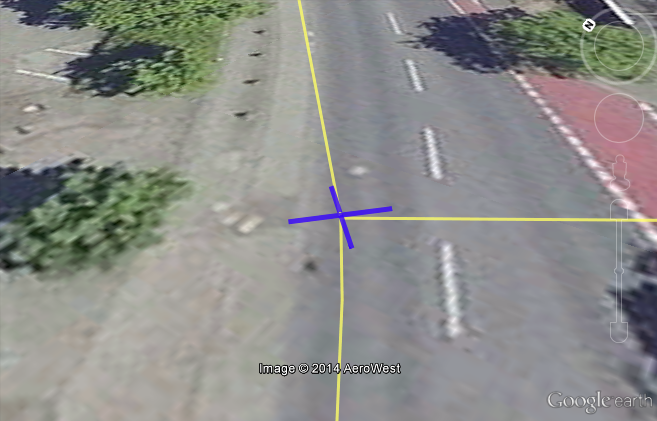
Fig. 3.50 An exported point geometry object displayed as a cross-line
- Icon: An alternative way for displaying point geometry in the earth browser is to use the KML’s native point placemark that can be represented with an icon in a user-defined color. The size of the icon can be determined with the help of the Scale option, where the default value is 1.0 (no scaling) which can give a fairly good perception.
Fig. 3.51 An exported point geometry object displayed as an icon
- Cube: Another possibility of representing the point geometry is to use a small solid particle whose central point should be identical to the target point. Similar to the options (Cross and Icon) described above, settings options for the size, color, and highlighting effect can also be adjusted to achieve an optimal visual effect.
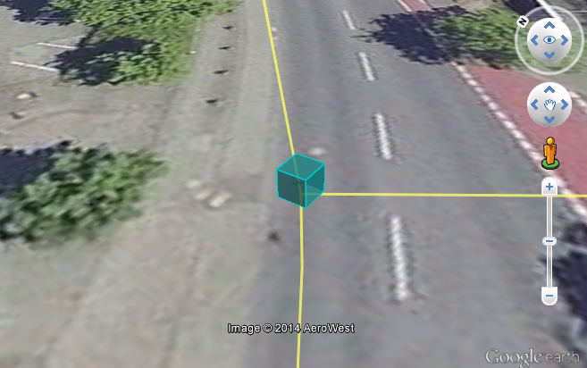
Fig. 3.52 An exported point geometry object displayed as a small cube
The rendering settings for the export of curve geometry objects can be configured in a similar manner as those of point geometry with the display form “Cross”.
Note
When displaying curve geometry objects in Google Earth, the altitude modes like absolute and relative may result in the curves intersecting with or hovering over the earth ground. If the user wants to keep the curve geometry objects always being draped on the earth ground, the altitude mode clamp to ground shall be chosen.
3.6.3.3. Information Balloon Preferences
KML offers the possibility of enriching its placemark elements with information bubbles, so-called balloons, which pop up when the placemark is clicked on. This is supported by the Importer/Exporter regardless of the display form in which the objects is exported.
Note
When exporting in the COLLADA display form it is recommended to enable the “highlighting on mouseOver” option, since model placemarks not coming from Google Earth servers are not directly clickable, but only through the sidebar. Highlighting geometries are, on the contrary, directly clickable wherever they are loaded from.
Note
If you want to use the 3DCityDB-Web-Map-Client (see Section 5 for more details) to visualize the exported datasets (KML/glTF models), the options (the both checkboxes shown in Fig. 3.53) for creating information balloons shall be deactivated, since the 3DCityDB-Web-Map-Client does not provide support for showing information balloons. In stead, it utilizes the online spreadsheet (Google Fusion Table) to query and display attribute information of the respective objects.
Balloon preferences can be set independently for each CityGML top-level feature type. That means every object can have its own individual template file (so that for instance, WaterBody balloons display a different background image as Vegetation balloons), and it is perfectly possible to have information bubbles for some object types while some others have none. For GenericCityObject, the point and line geometry object can also has its own individual balloon settings. The following example is set around Building balloons but it applies exactly the same for all feature classes.
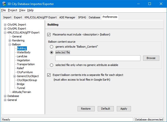
Fig. 3.53 Building Balloon settings
The contents of the balloon can be taken from a generic attribute called
Balloon_Content associated individually to each city object in the
3DCityDB. They can also be uniform for all objects in an export by using
an external HTML file as a template, or a combination of both:
individually and uniformly set, the Balloon_Content attribute
(individually) having priority over the external HTML template file
(uniform). A few Balloon HTML template files can be found after software
installation in the subfolder templates/balloons of the installation
directory.
The balloons can be included in the doc.kml file generated at export, or they can be put into individual files (one for each object) written together into a “balloon” directory. This makes later adaption work easier if some post-processing (manual or not) is required. When balloon contents are put into a separate file for each exported object, access to local files and personal data must be granted in Google Earth (Tools -> Options -> General) for the balloons to show.
The balloon contents do not need to be static. They can contain
references to the data belonging to the city object they relate to.
These references will be dynamically resolved (i.e.: the actual value
for the current object will be put in their place) at export time in a
way similar to how Active Server Pages (ASP) work.
Placeholders embedded in the HTML template, beginning with <3DCityDB>
and ending with </3DCityDB> tags, will be replaced in the resulting
balloon with the dynamically determined value(s). The HTML balloon
templates can also include JavaScript code.
For all concerns, including dynamic content generation, it makes no difference whether the template is taken from the Balloon_Content generic attribute or from an external file.
Balloon template format. As previously stated, a balloon template
consists of ordinary HTML, which may or may not contain JavaScript code
and <3DCityDB> placeholders for object-specific content. These
placeholders follow several elementary rules.
3.6.3.3.1. Rules for simple expressions
- Expressions begin with
<3DCityDB>and end with</3DCityDB>. Expressions are not case-sensitive. - Expressions are coded in the form
"TABLE/[AGGREGATION FUNCTION]
COLUMN [CONDITION]"
. Aggregation function and condition are optional. When present they must be written in square brackets (they belong to the syntax). These expressions represent an alternative coding of a SQL select statement:SELECT [AGGREGATION FUNCTION] COLUMN FROM TABLE [WHERE condition]. Tables refer to the underlying 3DCityDB table structure (see Section 2.7.2 for details). - Each expression will only return those entries relevant to the city
object being currently exported. That means an implicit condition
clause somewhat like
"TABLE.CITYOBJECT_ID = CITYOBJECT.ID"is always considered and does not need to be explicitly written. - Results will be interpreted and printed in HTML as lists separated by
commas. Lists with only one element are the most likely, but not
exclusively possible, outcome. When only interested in the first
result of a list the aggregation function FIRST should be used. Other
possible aggregation functions are
LAST,MAX,MIN,AVG,SUMandCOUNT. - Conditions can be defined by a simple number (meaning which element
from the result list must be taken) or a column name (that must exist
in underlying 3DCityDB table structure) a comparison operator and a
value. For instance:
[2]or[NAME = 'abc']. - Invalid results will be silently discarded. Valid results will be delivered exactly as stored in the 3DCityDB tables. Later changes on the returned results - like substring() functions - can be achieved by using JavaScript.
- All elements in the result list are always of the same type (the type
of the corresponding table column in the underlying 3DCityDB). If
different result types must be placed next to each other, then
different
<3DCityDB>expressions must be placed next to each other.
3.6.3.3.2. Special keywords in simple expressions
- The balloon template files have several additional placeholders for
object-specific content, called
SPECIAL_KEYWORDS. They refer to data that is not retrieved “as is” in a single step from a table in the 3DCityDB but has to undergo some processing steps (not achievable by simple JavaScript means) in order to calculate the final value before being exported to the balloon. A typical processing step is the transformation of some coordinate list into a CRS different from the one the 3DCityDB is originally set in. The coordinates in the new CRS cannot be included in the balloon with their original values as read from the database (which was the case with all other expression values so far), but must be transformed prior to their addition to the balloon contents. - Expressions for special keywords are not case-sensitive. Their syntax
is similar to ordinary simple expressions, start and end are marked
by
<3DCityDB>and</3DCityDB>tags, the table name must beSPECIAL_KEYWORDS(a non-existing table in the 3DCityDB), and the column name must be one of the following:
CENTROID_WGS84 |
coordinates of the object’s centroid in WGS84 in the following order:
longitude, latitude, altitude
|
CENTROID_WGS84_LAT |
latitude of the object’s centroid in WGS84
|
CENTROID_WGS84_LON |
longitude of the object’s centroid in WGS84
|
BBOX_WGS84_LAT_MIN |
minimum latitude value of the object’s envelope in WGS84
|
BBOX_WGS84_LAT_MAX |
maximum latitude value of the object’s envelope in WGS84
|
BBOX_WGS84_LON_MIN |
minimum longitude value of the object’s envelope in WGS84
|
BBOX_WGS84_LON_MAX |
maximum longitude value of the object’s envelope in WGS84
|
BBOX_WGS84_HEIGHT_MIN |
maximum longitude value of the object’s envelope in WGS84
|
BBOX_WGS84_HEIGHT_MAX |
maximum height value of the object’s envelope in WGS84
|
BBOX_WGS84_LAT_LON |
all four latitude and longitude values of the object’s envelope in WGS84
|
BBOX_WGS84_LON_LAT |
all four longitude and latitude values of the object’s envelope in WGS84
|
- No aggregation functions or conditions are allowed for
SPECIAL_KEYWORDS. If present they will be interpreted as part of the keyword and therefore not recognized. - The
SPECIAL_KEYWORDSlist is also visible and available in its current state in the updated version of the Spreadsheet Generator Plugin (see the following section). The list can be extended in further Importer/Exporter releases.
3.6.3.3.3. Examples for simple expressions
<3DCityDB>ADDRESS/STREET</3DCityDB>returns the content of the STREET column on the ADDRESS table for this city object.<3DCityDB>BUILDING/NAME</3DCityDB>returns the content of the NAME column on the BUILDING table for this city object.<3DCityDB>CITYOBJECT_GENERICATTRIB/ATTRNAME</3DCityDB>returns the names of all existing generic attributes for this city object. The names will be separated by commas.<3DCityDB>CITYOBJECT_GENERICATTRIB/REALVAL [ATTRNAME = 'H_Trauf_Min']</3DCityDB>returns the value (of the REALVAL column) of the generic attribute with attribute nameH_Trauf_Minfor this city object.<3DCityDB>APPEARANCE/[COUNT]THEME</3DCityDB>returns the number of appearance themes for this city object.<3DCityDB>APPEARANCE/THEME[0]</3DCityDB>returns the first appearance for this city object.<3DCityDB>SPECIAL_KEYWORDS/CENTROID_WGS84_LON</3DCityDB>returns the longitude value of this city object’s centroid longitude in WGS84.<3DCityDB>simple expressions can be used not only for generating text in the balloons, but any valid HTML content, like clickable hyperlinks:<a href="<3DCityDB>EXTERNAL_REFERENCE/URI</3DCityDB>"> click here for more information</a>returns a hyperlink to the object’s external reference
or embedded images:
<img src= "<3DCityDB>CITYOBJECT_GENERICATTRIB/URIVAL[ATTRNAME='Illustration']</3DCityDB>" width=400>
This last example produces, for instance, in the case of the Pergamon Museum in Berlin:
<img src="http://upload.wikimedia.org/wikipedia/commons/d/d1/FrisoaltarPergamo.jpg" width=400>
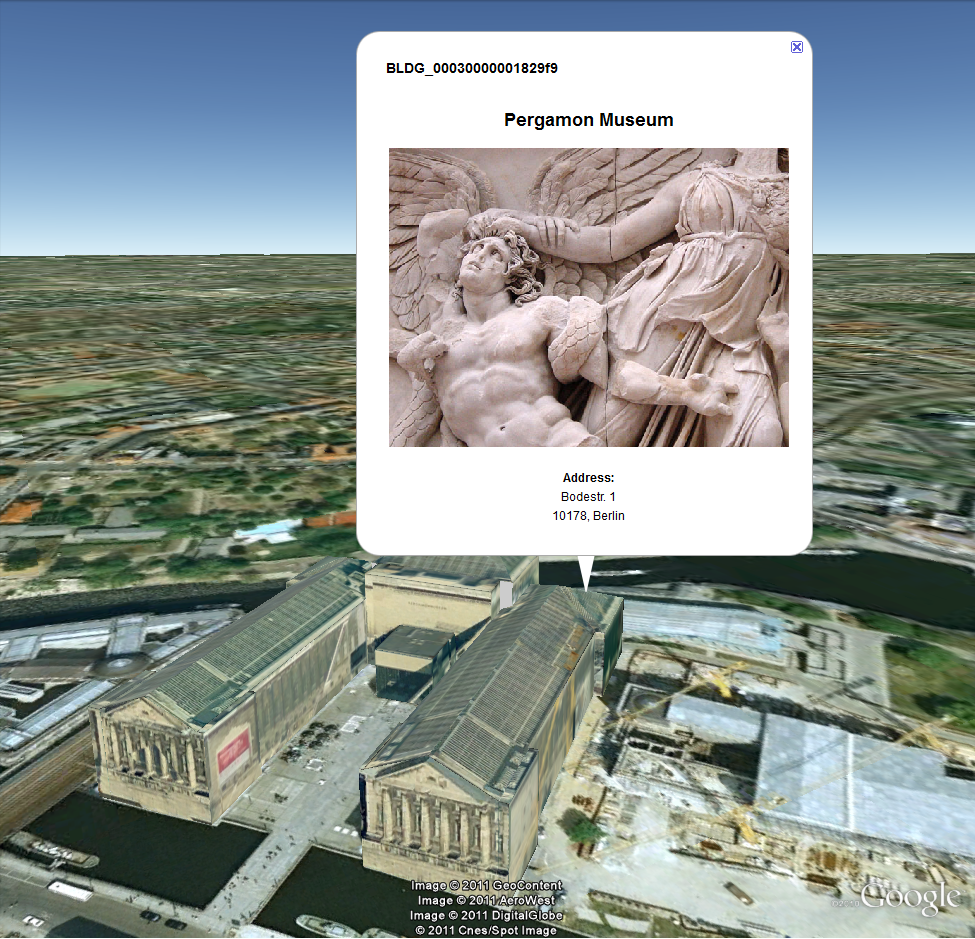
Fig. 3.54 Dynamically generated balloon containing an embedded image (image taken from Wikimedia)
Simple expressions are sufficient for most use cases, when only a single value or a list of values from a single column is needed. However, sometimes the user will need to access more than one column at the same time with an unknown amount of results. For these situations (listing of all generic attributes along with their values is one of them) iterative expressions were conceived.
3.6.3.3.4. Rules for iterative expressions
Iterative expressions will adopt the form:
<3DCityDB>FOREACH
      TABLE/COLUMN[,COLUMN][,COLUMN][...][,COLUMN][CONDITION]
</3DCityDB>
[...]
HTML and JavaScript code (column content will be referred to as %1, %2, etc. and follow the columns order in the FOREACH line. %0 is reserved for displaying the current row number)
[...]
<3DCityDB>END FOREACH</3DCityDB>
No aggregation functions are allowed for iterative expressions. The amount of columns is free, but they must belong to the same table. Condition is optional. Implicit condition (data must be related to the current city object) applies as for simple expressions.
FOREACHmeans truly “for each”. No skipping is possible. If skipping at display time is needed it must be achieved by JavaScript means.The generated HTML will have as many repetitions of the HTML code between the
FOREACHandEND FOREACHtags as lines the query result has.No inclusion of simple expressions or
SPECIAL_KEYWORDSbetweenFOREACHandEND FOREACHtags is allowed.No nesting of
FOREACHstatements is allowed.
3.6.3.3.5. Examples for iterative expressions
Listing of generic attributes and their values:
<script type="text/javascript">
      function ga_value_as_tooltip(attrname, datatype, strval, intval, realval) {
            document.write("<span title=\"");
            switch (datatype) {
                  case "1": document.write(strval);
                        break;
                  case "2": document.write(intval);
                        break;
                  case "3": document.write(realval);
                        break;
                  default: document.write("unknown");
            };
            document.write("\">" + attrname + "</span>");
      }
      <3DCityDB>FOREACH
            CITYOBJECT_GENERICATTRIB/ATTRNAME,DATATYPE,STRVAL,INTVAL,REALVAL</3DCityDB>
            ga_value_as_tooltip("%1", "%2", "%3", "%4", "%5");
      <3DCityDB>END FOREACH</3DCityDB>
</script>
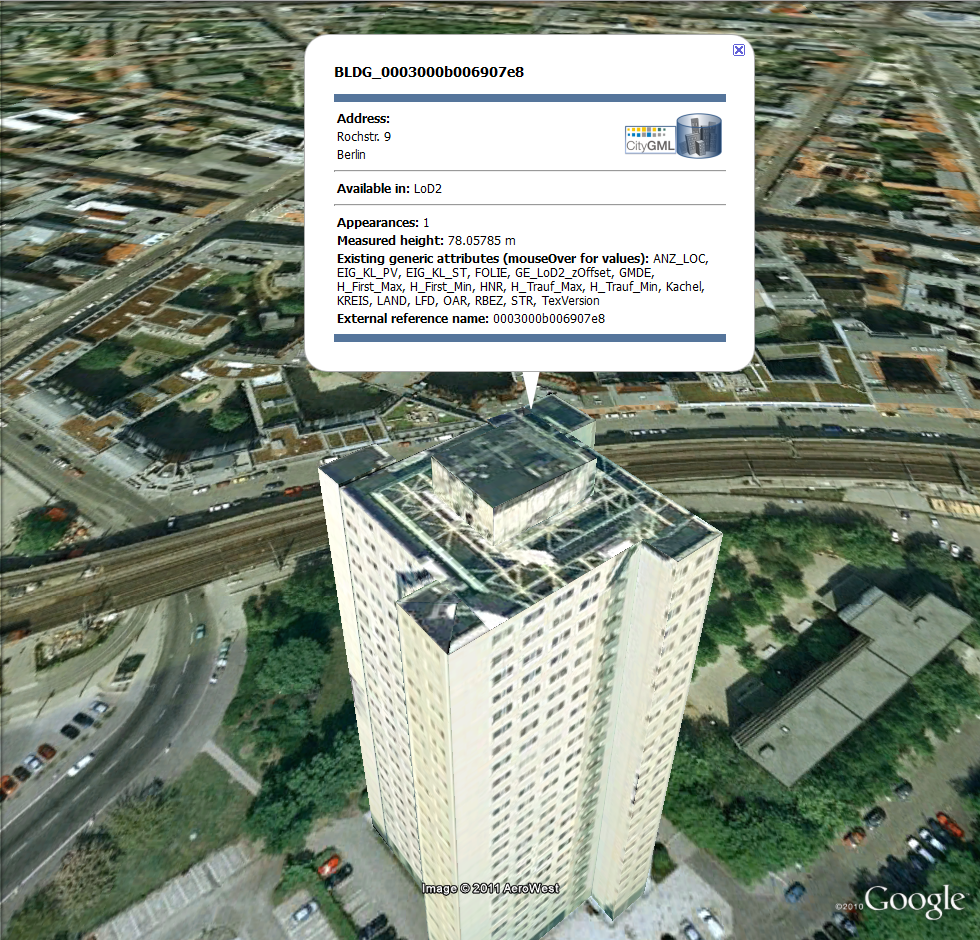
Fig. 3.55 Model placemark with dynamic balloon contents showing the list of generic attributes
3.6.3.4. Altitude/Terrain Preferences
In order to ensure a perfect display of the exported datasets in the Earth browser, some adjustments on the z coordinate for the exported 3D objects may be necessary.
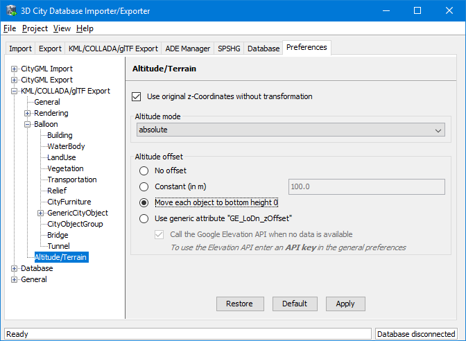
Fig. 3.56 Altitude/Terrain settings
3.6.3.4.1. Use original z-Coordinates without transformation
Depending on the spatial database used, the transformation of the original coordinates to WGS84 will include transformation of the z-coordinates (PostGIS starting from version 2.0 or Oracle starting from version 11g) or not (Oracle 10g). To make sure only the planimetric (x,y) and not the z-coordinates are transformed this checkbox must be selected. This is useful when the used terrain model is different from Google Earth’s and the z-coordinates are known to fit perfectly in that terrain model.
Another positive side-effect of this option is that GE_LoDn_zOffset attribute values (explained in the following section) calculated for Oracle 10g keep being valid when imported into PostGIS starting from version 2.0 or Oracle starting from version 11g. Otherwise, when switching database versions and not making use of this option, GE_LoDn_zOffset values must be recalculated again.
GE_LoDn_zOffset attribute values calculated for Oracle 10g are consistent for all KML/COLLADA/glTF exports from Oracle 10g. The same applies to PostGIS starting from version 2.0 or Oracle starting from version 11g. Only cross-usage (calculation in one version, export from the other) creates inconsistencies that can be solved by turning z-coordinate transformation off.
This setting affects the resulting GE_LoDn_zOffset if used when a cityobject has none such value yet and is exported in KML/COLLADA for the first time, so it is recommended to remember its status (z-coordinate transformation on or off) for all future exports.
3.6.3.4.2. Altitude mode
Allows the user to choose between relative (to the ground), interpreting the altitude as a value in meters above the terrain, or absolute, interpreting the altitude as an absolute height value in meters according to the vertical reference system used by the Earth browser (e.g., Google Earth uses the EGM96 geoid, whereas Cesium uses the WGS84 ellipsoid), or clamp to ground, which allows the exported objects to be always clamped to ground.
This means, when relative altitude mode is chosen, the z-coordinates of the exports represent the vertical distance from the digital terrain model (DTM) of the Earth browser, which should be 0 for those points on the ground (the building’s footprint) and higher for the rest (roof surfaces, for instance). However, z-coordinate values of the city objects stored in a 3DCityDB usually have values bigger than 0, so choosing this altitude mode will often result in exports hovering over the ground.
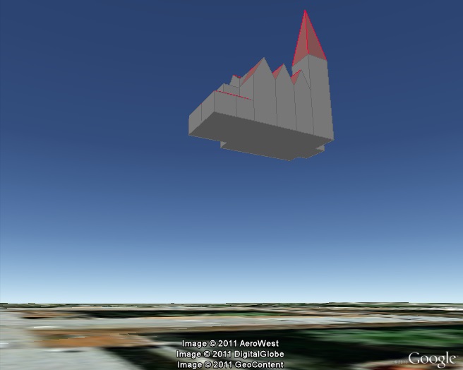
Fig. 3.57 Possible export result with relative altitude mode
When absolute altitude mode is chosen, the z-coordinates of the exports represent the vertical distance from the vertical datum - the ellipsoid or geoid which most closely approximates the Earth curvature, regardless of the DTM at that point. This implies, choosing this altitude mode may result in buildings sinking into the ground wherever the DTM indicates there is a hill or hovering over the ground wherever the DTM indicates a dent.
When the clamp to ground altitude mode is chosen, the z-coordinate values of the exported objects will be ignored and every surface geometry of the KML models will be forced to lie on the surface of the ground.
For a proper grounding, the Altitude offset setting can additionally be used so that a positive or negative offset value can be applied to all z-coordinates of the exports, moving the city objects up and down along the z-axis until they match the ground.
Note
Both Altitude mode and Altitude offset settings will only take effect when the city objects are exported in the Geometry or COLLADA/glTF display forms. When, for example, the Footprint display form is selected, The KML/COLLADA/glTF-Exporter will internally use the clamp to ground altitude mode to ensure that the exported geometries will be always clamped to ground regardless of the altitude mode chosen by the user. Likewise, when exporting in the Extruded display form, the relative altitude model will be internally applied and the height value of the respective city object will be used to represent the relative height above the ground.
3.6.3.4.3. Altitude offset
A value, positive or negative, can be added to the z coordinates of all geometries in one export in order to place them higher or lower over the earth surface. This offset can be 0 for all exported objects (no offset), it can be constant for all (constant), or it can have an individual value for each object to ensure that the bottom of the object is placed on the earth surface.
The first option no offset implies that the z-coordinates of all geometries are kept unchanged at export time if the option Use original z-Coordinates without transformation is selected. The second option constant is particularly appropriate for exports of a single city object, allowing some fine-tuning of its position along the z-axis.
When exporting regions - via bounding box settings -, the other two options, Move each object to bottom height 0 and Use generic attribute “GE_LoDn_zOffset”, are recommended.
Once the option Move each object to bottom height 0 is selected, the elevation value of the lowest point for every object will be calculated and its inversed value should exactly equal to the zOffset value of the respective object. This zOffset value will be used for adjusting the z- coordinates of the object to ensure that its lowest point has a height of 0 meter. This setting is particularly advisable, since combined with the relative altitude mode the exported objects can always be properly placed on the ground in Google Earth regardless of whether its terrain layer is activated or not. However, if the absolute altitude is chosen, a proper grounding of the objects requires that the terrain layer in Google Earth must be deactivated.
Note
Regardless of the chosen altitude mode, the Cesium-based 3DCityDB-Web-Map-Client always interprets the altitude as an absolute height value in meters according to the WGS84 ellipsoid reference system. Thus, the option Move each object to bottom height 0 can only ensure a proper grounding of the objects on the Cesium Virtual Globe when its WGS84 ellipsoid terrain model (default) is activated.
When choosing the absolute altitude model and displaying city objects
on Google Earth with enabled terrain layer, the option Use generic
attribute “GE_LoDn_zOffset” shall be selected. Here the
GE_LoDn_zOffset generic attribute value can be automatically
calculated by the Importer/Exporter if not available. This calculation
uses data returned by
Google’s Elevation API.
After completing the calculation, the results will be stored in
the CITYOBJECT_GENERICATTRIB table of the 3DCityDB for future use.
Note
Starting from July 2018, an Elevation API key is required in order to enable access to the Google Elevation Service. Thus, the option Call the Google Elevation API when no data is available should only be enabled when a valid Elevation API key is available. Users can provide their own Elevation API key in the general preferences as described in Section 3.6.5.4. For more details on the Google Maps Platform Terms of Service, please refer to https://cloud.google.com/maps-platform/terms/.
Since city objects may have different geometries for different LoDs, the anchoring points and their elevation values may also differ for each LoD. This explains the need for having GE_LoD1_zOffset, GE_LoD2_zOffset, etc. generic attributes for one single object.
The algorithm used to calculate the individual zOffset for an object iterates over the points with the lowest z-coordinate in the object, calling Google’s elevation API in order to get their elevation. The point with the lowest elevation value will be chosen for anchoring the object to the ground. The zOffset value results from subtracting the point’s z-coordinate from the point’s elevation value.
When calling Google’s elevation API for calculating the zOffset of an object a message is shown: “Getting zOffset from Google’s elevation service for BLDG_0003000e008c4dc4”.
Saving the building’s height offset in the form of a generic attribute ensures this information will be present in every export in CityGML format (and therefore at every re-import) and can thus be transported across databases. Please note, that not the DTM height value of Google Earth will be stored but the difference of the individual building’s minimum z value and the value reported by the Google Elevation Service. Following this approach further usage restrictions of the Google Elevation Service are avoided.
In some unusual cases, even after automatic calculation of the GE_LoDn_zOffset value the object may still not be perfectly grounded to the Earth surface for a number of reasons; e.g. wrong height data of the model, or low resolution of the DTM at that area. In those cases a manual adjustment of the value in the 3DCityDB is needed. After the content of GE_LoDn_zOffset has been fine-tuned to a proper value it should be persistently stored in the database.
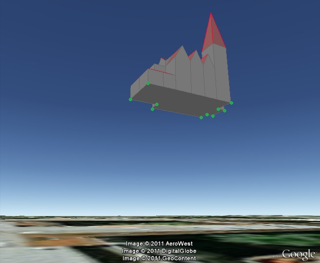
Fig. 3.58 Points sent to Google’s Elevation API for calculation of the zOffset
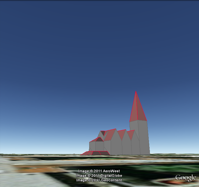
Fig. 3.59 Export with absolute altitude mode and no offset
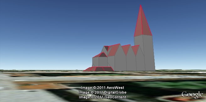
Fig. 3.60 Export with absolute altitude mode and use of GE_LoDn_zOffset
3.6.3.5. General setting recommendations
Depending on the quality and complexity of the 3DCityDB data, export results may vary greatly in aesthetic and loading performance. Experimenting will be required in most cases for a fine-tuning of the export parameters. However, some rules apply for almost all cases:
- kmz format use is recommended when the files will be accessed over a network and the selected display form is Footprint, Extruded, or Geometry. In case of glTF-export, only kml format is allowed.
- Visibility values for the different display forms should be increased in steps of around one third of the tile side length.
- Visibility from 0 pixels (always visible) should be avoided, especially for large or complex exports, because otherwise the Earth browser will immediately load all data at once since it all must be visible.
- Tile side length (whether tiling is automatic or manual) should be chosen so that the resulting tile files are smaller than 10MB. When single files are bigger than that Google Earth gets unresponsive. For densely urbanized areas, where many placemarks are crimped together a tile side length value between 50 and 100m should be used.
- When not exporting in the COLLADA/glTF display form, files will seldom reach this 10MB size, but Earth browser will also become unresponsive if the file loaded contains a lot of polygons, so do not use too large tiles for footprint, extruded or geometry exports even if the resulting files are comparatively small.
- Do not choose too small tile sizes, many of them may become visible at the same time and render the tiling advantage useless.
- Using texture atlas generation when producing COLLADA/glTF display form exports always results in faster model loading times.
- From all texture atlas generating algorithms, BASIC is the fastest (shortest generation time), TPIM the most efficient (highest used area/total atlas size ratio).
- Texture images can often be scaled down to 0.2 - 0.5 without noticeable quality loss. This depends, of course, on the quality of the original textures.
- Highlighting puts the same polygons twice in the resulting export files, one for the buildings themselves, one for their highlighting. This has a negative impact on the viewing performance. The more complex the buildings are the worse the impact. When highlighting is enabled for exports based on a CityGML LoD3 or higher Google Earth may become quite slow.
- If you want to use the 3DCityDB-Web-Map-Client to visualize the exported datasets, options for creating highlighting geometries should not be chosen, since the highlighting functionality is already well-supported by the 3DCityDB-Web-Map-Client which requires no extra highlighting geometries.
- The 3DCityDB-Web-Map-Client allows for on-the-fly activating and deactivating shadow visualization of 3D objects exported in the glTF format. However, this functionality is currently not available when viewing KML models exported in the Footprint, Extruded, and Geometry display forms.
- Balloon generation is slightly more efficient when a single template file is applied for all exported objects.
- When exporting in the Footprint or Extruded display forms, the altitude/terrain settings will be silently ignored by the KML/COLLADA/glTF-Exporter which will instead internally applies the appropriate altitude models to the exported objects to ensure that they will be properly placed on the ground in Earth browsers. However, when exporting in the Geometry or COLLADA/glTF display forms, the altitude/terrain settings must be properly adapted regarding the Earth browsers to be used.
- In most cases, the combination of the relative altitude mode with the Move each object to bottom height 0 altitude offset allows for a proper grounding and displaying of the objects in Earth browsers. However, when using the Cesium-based 3DCityDB-Web-Map-Client, its default WGS84 ellipsoid terrain model must be activated.
- When using the absolute z-coordinates and displaying the exported datasets together with terrain layer in Google Earth, you need to choose the following combination of settings, should you have a valid Goole Elevation API key: absolute altitude mode, generic attribute “GE_LoDn_zOffset”, and call Google’s elevation API when no data is available.