4.6.7.2. Styling
The Styling preferences allow you to define colors and symbols to be used for the visualization of the exported city objects. Styles can be defined for each top-level feature type separately on different subnodes of the Styling preference node. If an ADE extension is registered with the Importer/Exporter that supports exporting ADE features for visualization, additional subnodes for each ADE top-level feature type are automatically added and available.
4.6.7.2.1. Styling of surface and solid geometries
The styling options for surface and solid geometries of city objects are explained in the following using the preferences dialog of the Building feature type as shown below. This dialog offers the most settings of all feature types. The only exceptions are the dialogs for GenericCityObject and ADE top-level feature types, which provide additional styling options for point and curve geometries (see Section 4.6.7.2.2).
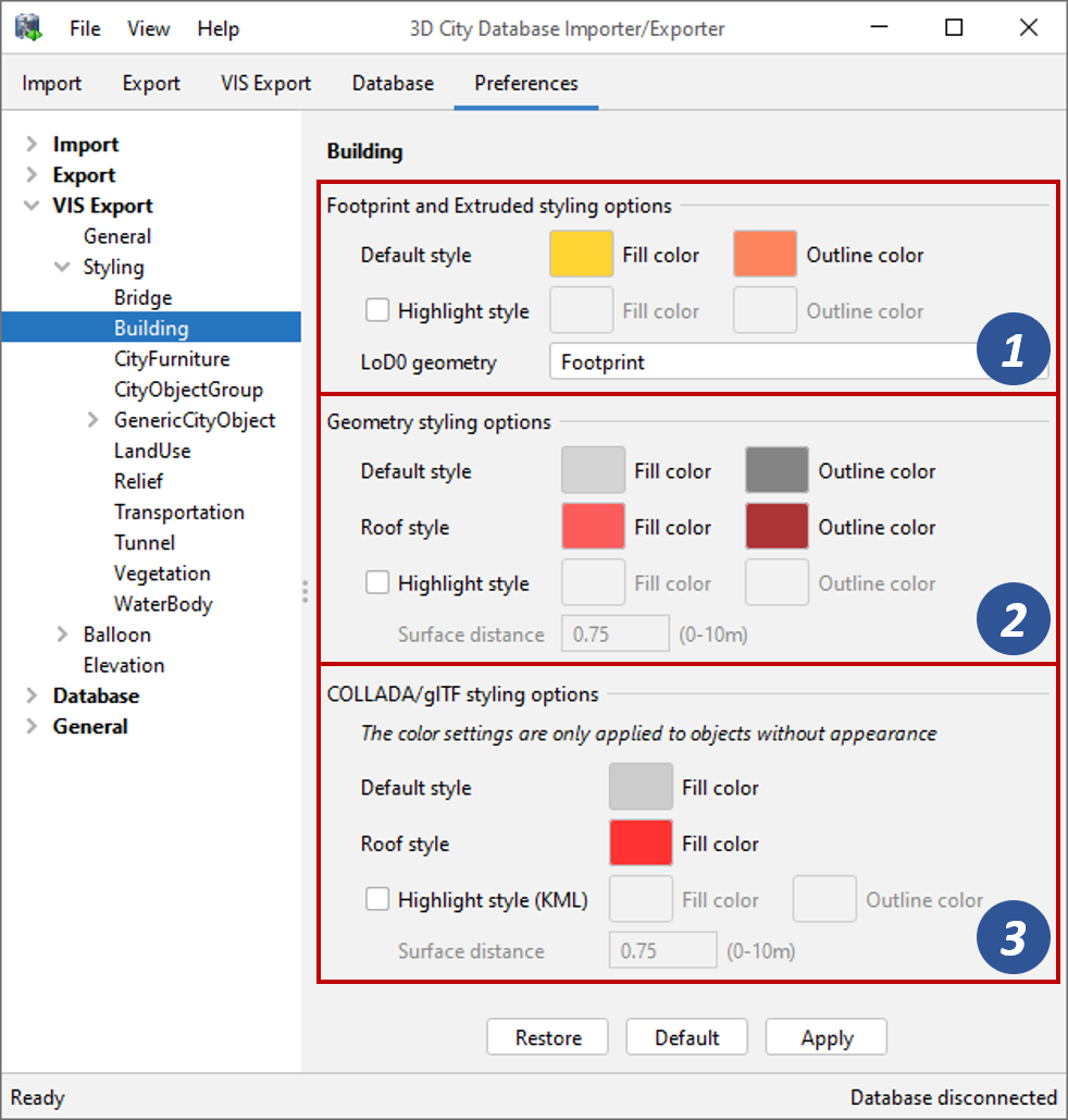
Fig. 4.62 Visualization export preferences – Styling options.
The dialog lets you define different styles for the different display forms offered by the visualization export (see Section 4.6). The styling options are therefore grouped into Footprint and Extruded [1], Geometry [2], and COLLADA/glTF [3].
Default style and highlight style
All styling options for the different display forms have in common that you can specify a default style and an optional highlight style. For feature types that can be modelled with roof surfaces such as buildings, bridges and tunnels an additional roof style is available for the Geometry and COLLADA/glTF display forms.
A style consists of a fill color and an outline color that are used for rendering the surfaces of a corresponding city object. Only in case of the COLLADA/glTF display form, outline colors are not supported for the default and roof styles. To choose a color, simply click on the button for the fill or outline color. This brings up a default color selection dialog where you can either pick a color from a palette or enter a HSV, HSL, RGB or CMYK color code. Note that you can also define an alpha/transparency value for your color. After accepting the selected color, it is also used as new color for the button in the dialog. This way, you have an immediate visual feedback of the color that will be applied in the visualization export.
Both the default style and the roof style are immediately applied when a city object is loaded and becomes visible in the viewer. The highlight style, however, is only shown when hovering the mouse over a city object. This highlighting effect is realized by duplicating all surfaces of the feature and assigning the chosen highlight color to these duplicates. The resulting “highlight geometry” is stored as additional KML geometry for each feature and is loaded together with the feature but set to invisible by default.
For the display forms Geometry and COLLADA/glTF, an additional Surface distance value between 0 and 10 meters (default: 0.75) can be defined to make sure that the original surfaces and their duplicates are not coincident. The highlight surface is moved along the direction if its face normal by the provided distance value. This way, the highlight geometry realizes an “exploded” view of the city object, which helps to avoid Z-fighting effects.
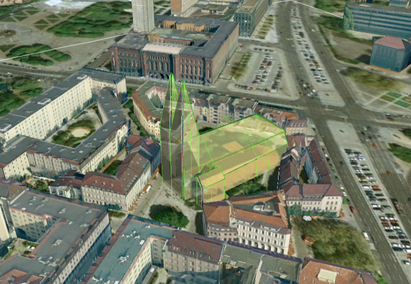
Fig. 4.63 Example of the highlight style in Google Earth.
Note
Since the highlight geometry duplicates the original feature geometry, it has a significant impact on loading times and may also impair the general visualization performance.
Note
The highlight style has been mainly developed for use with Google Earth and directly works with this viewer. The 3D web map client shipped with the 3D City Database (see Section 6) does not support the highlight geometry but uses Cesium functionalities for object highlighting. If you intend to use the export with the 3D web map client only, disable the highlight geometry.
Footprint and Extruded styling options
In addition to the definitions of colors for the different styles, the Footprint and Extruded settings let you choose the LoD0 geometry that shall be used for rendering buildings when LoD0 is used as target LoD for the visualization export on the VIS Export tab. Note that this selection is only available for the Building feature type but not for other feature types. The following options are available for the LoD0 geometry:
- Footprint: The footprint geometry of buildings will be used for visualization.
- Roofprint: The roofprint geometry of buildings will be used for visualization.
- Roofprint - use footprint as fallback: Roofprint geometries will be used in the first place. If no roofprint geometry is available, the footprint geometry is used as fallback.
Geometry styling options
As mentioned above, an additional roof style can be defined for the Geometry display form if the corresponding feature type supports roof surfaces (i.e., buildings, bridges, and tunnels). The roof style is applied to the surface geometries of all roof surfaces modelled for the city object. The default style is used for all other surfaces.
Especially for buildings, users often want to have roofs painted in a different color than walls even if roof surfaces are not explicitly modelled for the building. For this reason, the export process uses simple heuristics to identify roofs purely based on the geometry of the building: surfaces touching the ground (i.e., having the lowest height values) are considered to be walls and receive the default style. All other surfaces are classified as roofs and receive the roof style.
Note
The automatic detection of roof surfaces is only applied to buildings, and only if the building is to be exported in LoD1 or LoD2. Surfaces that are explicitly modelled as roof or wall surface in the model are, of course, excluded from the automatic detection.
COLLADA/glTF styling options
In contrast to the display forms Extruded, Footprint and Geometry, a user can select an appearance theme for COLLADA/glTF exports on the VIS export tab to apply appearance data stored in the 3DCityDB to the surfaces of the exported city objects (see Section 4.6). Appearance data not only comprises textures but also colors. Thus, textures and colors assigned to a surface through the selected appearance theme always take precedence over the styles defined for the COLLADA/glTF display form on this preferences dialog.
As mentioned above, outline colors cannot be defined for the default style and the roof style because they are not supported by the COLLADA and glTF formats. Similar to the Geometry styling options, the roof style is only available for feature types that support roof surfaces, and an automatic roof detection is applied to buildings in accordance with the rules discussed above.
4.6.7.2.2. Styling of point and curve geometries
GenericCityObject features can also be modelled and stored with point and curve geometries in addition to a surface-based representation. Point and curve geometries can be exported in KML format by the visualization export operation. Thus, they are supported by the KML-based display forms Footprint, Extruded and Geometry but not when exporting to COLLADA/glTF.
The styling preferences for the GenericCityObject feature type therefore not only provide a dialog for surface and solid geometries as described above, but also for point and curve geometries as shown below.
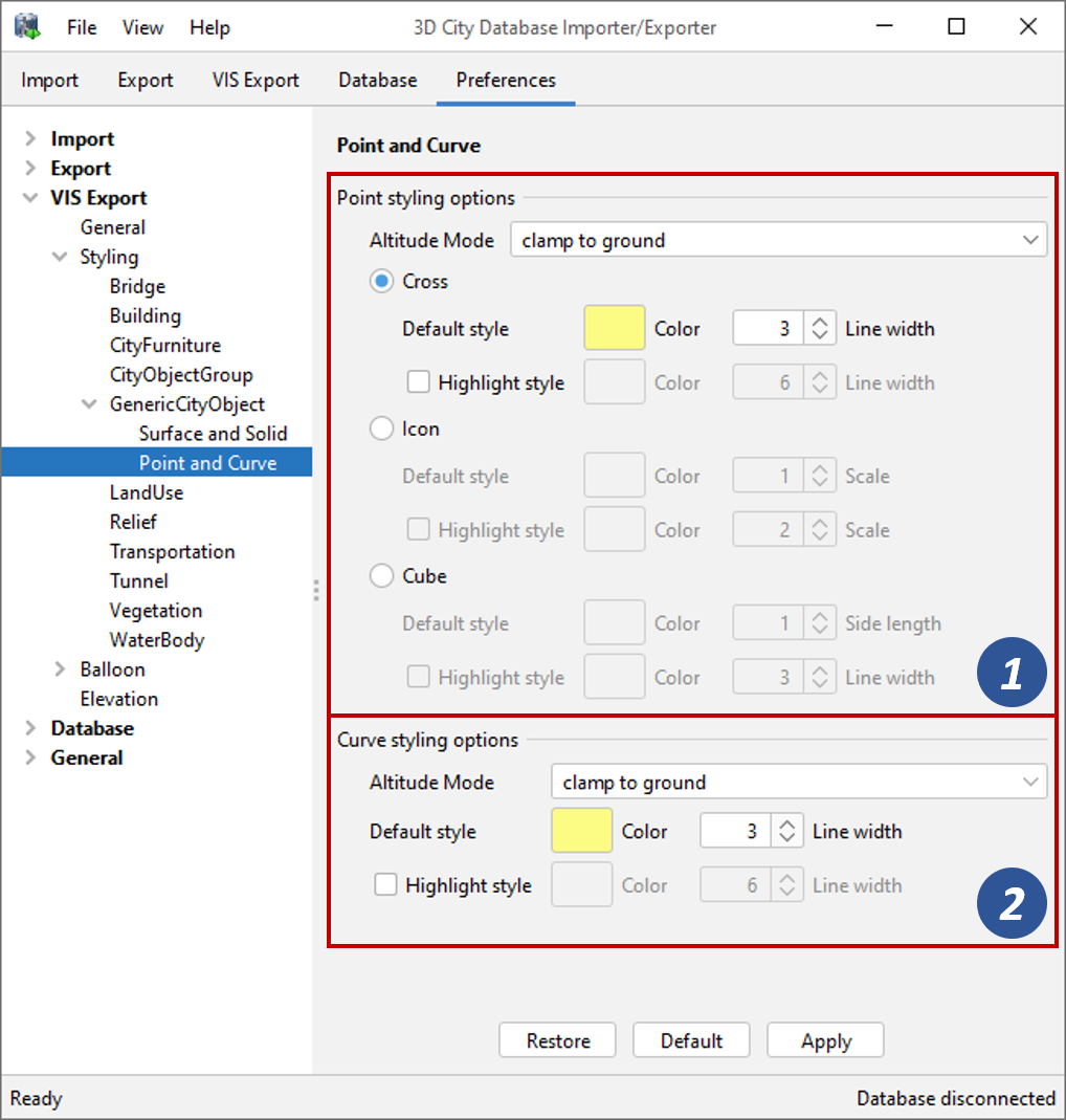
Fig. 4.64 Styling options for point and curve geometries of GenericCityObject features.
Note
Similar to the GenericCityObject feature type, also the preferences for ADE top-level feature types offer styling options for surface and solid geometries and for point and curve geometries.
Point styling options
Point geometries are visualized by rendering a symbol at the point location. You can choose between a cross, an icon and a cube symbol as visual representation of the point geometry [1]. For each symbol, a separate default style and optional highlight style can be defined.
The Altitude Mode parameter specifies how the height values (altitude) of the exported point geometries are to be interpreted by a viewer or application.
Altitude mode
|
Description
|
relative
|
The altitude is interpreted as a value in meters above the terrain. The absolute height value can be determined by adding the terrain elevation.
|
absolute
|
The altitude is interpreted as an absolute height value in meters according to the vertical reference system (EGM96 geoid in Google Earth, WGS84 ellipsoid in Cesium).
|
clamp to ground
|
The altitude will be ignored and the point geometry will always be clamped to the ground.
|
The three different symbol types offer the following additional settings.
- Cross
- When choosing the cross symbol, the point geometry is visualized as crosshair with a length of approx. 2 meters. This length value cannot be customized. However, you can pick an additional line width for both the default and the highlight style.
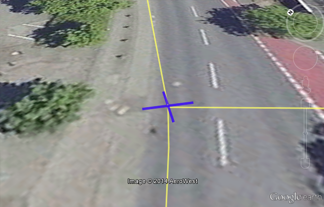
Fig. 4.65 A point geometry displayed as cross symbol.
- Icon
- The icon symbol uses a KML
<Placemark>element with the point geometry and displays an icon at this position. Besides the color of the icon, also its size can be defined for both the default and the highlight style using the Scale parameter, where the default value 1 means no scaling.
Fig. 4.66 An point geometry displayed as icon symbol.
- Cube
- The third symbol for representing a point geometry is cube. In this case, a small cube is rendered at the point location. You can define the the side length for the cube for the default style, which will also be applied to the highlight style. In addition, you can define the Line width of the cube’s outline for the highlight style (a value of 1.0 is used for the default style).
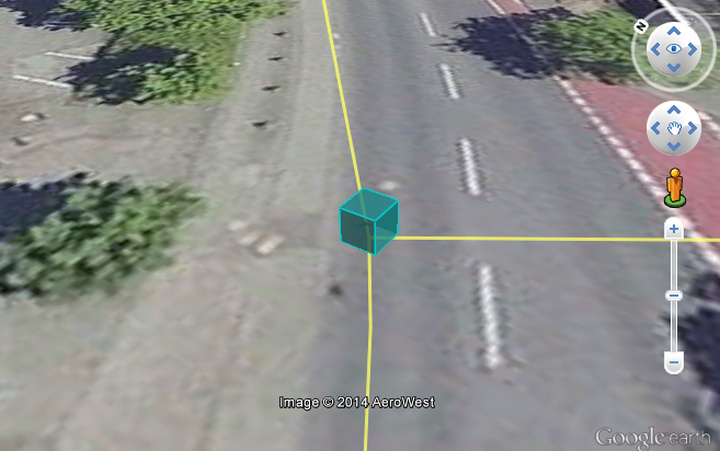
Fig. 4.67 A point geometry displayed as cube symbol.
Curve styling options
The styling options for curve geometries [2] are similar to those for the cross symbol of point geometries. And like with point geometries, you can also define a separate Altitude mode for curve geometries. The values and their meanings are identical to those described above in Table 4.22.
Note
When displaying curve geometries in Google Earth, the altitude modes absolute and relative may result in curves intersecting with or hovering over the terrain. Please choose clamp to ground if you want the curve geometries to be draped on the terrain instead.
The following figure exemplifies the visualization of point and curve geometries in Google Earth. It shows an indoor routing network for a building on the campus of the Technical University Munich (TUM). The nodes and edges of this network are modelled as GenericCityObject features with 3D point and curve geometries. The nodes are displayed using the cube symbol.
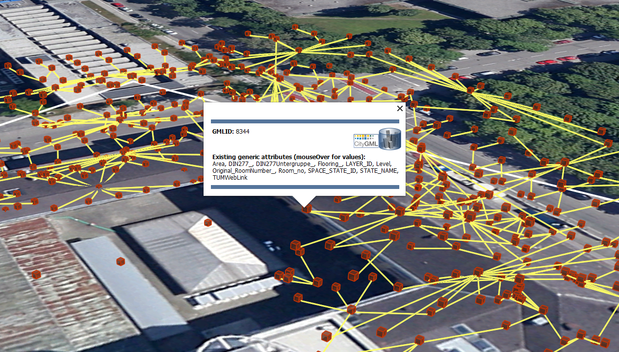
Fig. 4.68 Visualization of a network model of the building interior of Technical University Munich (TUM).